That is so interesting. This seems like it is a time-usage-based failure. I was also running for 24h I believe before failure. For all those engineers on this thread, what causes that? Also where is the best place (in stock) to source a new one?I run 24/7. The 30% was keeping me at right around 7ppm.

Pentair ic40, surge board, intelliph and swg transformer.
- Thread starter Latitude22
- Start date
You are using an out of date browser. It may not display this or other websites correctly.
You should upgrade or use an alternative browser.
You should upgrade or use an alternative browser.
")
- Jul 21, 2013
- 52,852
- Pool Size
- 35000
- Surface
- Plaster
- Chlorine
- Salt Water Generator
- SWG Type
- Pentair Intellichlor IC-60
That is so interesting. This seems like it is a time-usage-based failure. I was also running for 24h I believe before failure. For all those engineers on this thread, what causes that? Also where is the best place (in stock) to source a new one?
My WAG is it is caused by continuous heat from constant running giving the socket area no time to cool down. A bit of corrosion causing resistance in the socket connection would cause the heating.
Versus a run time that causes heating and then a cool down cycle when the pump and cell are off.
I would bet that Pentair engineers never tested the boards with continuous 24 hour running of the SWG and corrosion in the socket.
It's official. The report, submitted to the CPSC, is now visible publicly. Here is the product desciption - SaferProducts
Flying Tivo
TFP Guide
- Jan 24, 2017
- 2,959
- Pool Size
- 7500
- Surface
- Plaster
- Chlorine
- Salt Water Generator
- SWG Type
- Pentair Intellichlor IC-40

- Nov 12, 2017
- 11,876
- Pool Size
- 12300
- Surface
- Plaster
- Chlorine
- Salt Water Generator
- SWG Type
- Pentair Intellichlor IC-40
Given Pentair has admitted there is a problem with the IntellipH and an IC60, without actually recalling the product, this action was probably past due. It'll be interesting to see if anything comes of it.It's official. The report, submitted to the CPSC, is now visible publicly. Here is the product desciption - SaferProducts
I had a very similar failure of both intelliph and surge board. Pics look almost identical to mine! I posted on aother post with my issue but found this one tagged by the electronics guru.Not only is there room on the bus, but we're gonna scoot back because you get to sit in the front seat. I think yours is the first we've seen of the IpH AND the surge board fried like that. Pentair has been admitting to the IC60 problem for a while now. We've shown here that the IC40 is also causing the same problem, with both the IntellipH and the surge board, but apparently Pentair is in denial about that (or just mum about it).
You're in good hands with Tom (ogdento) but there might be a new board or two in your future. Tom is looking into getting some of the current running through all this junk to do so off the board(s) somehow, and just running the much lower-current comm traffic through the board(s). You know, something Pentair should be doing!
Up to Tom if he needs another board or two, but thanks for offering. Between the growing number of us, we should be able to add up to at least most of one good brain!
Sorry for your bad luck...

- Nov 12, 2017
- 11,876
- Pool Size
- 12300
- Surface
- Plaster
- Chlorine
- Salt Water Generator
- SWG Type
- Pentair Intellichlor IC-40
I just posted in that other thread some illustrations that depict what we think is the fix for this, or at least the fix for part of the problem.I had a very similar failure of both intelliph and surge board. Pics look almost identical to mine! I posted on aother post with my issue but found this one tagged by the electronics guru.
- Jun 17, 2019
- 23
- Pool Size
- 15800
- Surface
- Plaster
- Chlorine
- Salt Water Generator
- SWG Type
- Pentair Intellichlor IC-40
Well here I am two years later and the same spots again have burned out on the board. Seems like I get 2 years out of that acid board and it melts. I’m done, removing the entire acid injector setup and I guess I’ll just add acid manually from here on out. It’s not worth the expense
- May 3, 2014
- 58,477
- Pool Size
- 6000
- Surface
- Fiberglass
- Chlorine
- Salt Water Generator
- SWG Type
- Pentair Intellichlor IC-40
Do you have automation? Convert the tank to an on demand pump system.
- Nov 12, 2017
- 11,876
- Pool Size
- 12300
- Surface
- Plaster
- Chlorine
- Salt Water Generator
- SWG Type
- Pentair Intellichlor IC-40
A few here have abandoned the IntellipH controller and just use the tank and pump and a circuit on their pool automation controller to dispense automatically. I still use my IpH controller, but with a trick of wiring I run the tank using my pool automation controller during the winter. It works just fine.Well here I am two years later and the same spots again have burned out on the board. Seems like I get 2 years out of that acid board and it melts. I’m done, removing the entire acid injector setup and I guess I’ll just add acid manually from here on out. It’s not worth the expense
If you're interested in abandoning the controller but running the tank another way, we can help you figure out how.
- Jun 17, 2019
- 23
- Pool Size
- 15800
- Surface
- Plaster
- Chlorine
- Salt Water Generator
- SWG Type
- Pentair Intellichlor IC-40
Interesting idea I hadn’t even thought of that. I ended up ordering a brand new intelliph pcb which has a new board slightly different from the last one. They I cut the plug of the the board and soldered directly to the pins and shrink tubes then to isolate them and so far so good. We shall see if lasts longer than 2 years. If not i will probably give this suggestion a try. Both the surge board and the intelliph board are noticeably different. So I don’t know maybe they have improved them we shall see.A few here have abandoned the IntellipH controller and just use the tank and pump and a circuit on their pool automation controller to dispense automatically. I still use my IpH controller, but with a trick of wiring I run the tank using my pool automation controller during the winter. It works just fine.
If you're interested in abandoning the controller but running the tank another way, we can help you figure out how.
- Nov 12, 2017
- 11,876
- Pool Size
- 12300
- Surface
- Plaster
- Chlorine
- Salt Water Generator
- SWG Type
- Pentair Intellichlor IC-40
We would really like to see a picture of that, the next time you're snooping around inside the controller.Interesting idea I hadn’t even thought of that. I ended up ordering a brand new intelliph pcb which has a new board slightly different from the last one. They I cut the plug of the the board and soldered directly to the pins and shrink tubes then to isolate them and so far so good. We shall see if lasts longer than 2 years. If not i will probably give this suggestion a try. Both the surge board and the intelliph board are noticeably different. So I don’t know maybe they have improved them we shall see.
- Jun 17, 2019
- 23
- Pool Size
- 15800
- Surface
- Plaster
- Chlorine
- Salt Water Generator
- SWG Type
- Pentair Intellichlor IC-40
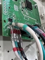
I snapped this photo of my solder job. I did it differently than other folks here. I didn’t want to drop down a wire size so I cut the pints and the soldered directly to the pins. The issue is the real changes are right behind those wires. Instead if the little white relay it’s not a larger black relay. Also the faceplate changed graphics slightly from my last one.
Attachments
- Nov 12, 2017
- 11,876
- Pool Size
- 12300
- Surface
- Plaster
- Chlorine
- Salt Water Generator
- SWG Type
- Pentair Intellichlor IC-40
Thanks for the pic. Your typo threw me. You wrote "They I cut the plug of the the board and soldered directly to the pins..." when I think you meant "Then I cut..." I thought you meant Pentair was now soldering onto the board. Oh well, just wishful thinking. Looks like you did a good job, better than mine (I soldered to the board, too).
I got the pins too hot and they came off the board. So I had to solder the fat wires to the remaining holes in the board, without flowing solder between the holes. No easy feat. In fact, I was sure I had fried something in the board, getting it too hot. I was pleasantly surprised that it was fine when I fired it up.
Mine has been running fine for just over two years now. The only thing I would have done differently (and should, someday) is to connect the red to the red and the black to the black an inch or two back from the board. This will create a better path for the current, so that it doesn't all have to run through the traces of the board. It's probably fine doing so (it has been), it just seems like a prudent precaution.
Did you somehow leave the four lower connections alone? Just removing the surrounding plastic of the connector? That was smart. I botched the whole thing and ended up having to solder all eight fat wires to the board, which made the process that much more difficult, and got the board that much hotter.
- Jun 17, 2019
- 23
- Pool Size
- 15800
- Surface
- Plaster
- Chlorine
- Salt Water Generator
- SWG Type
- Pentair Intellichlor IC-40
Yea sorry for the typo so what i did was did a trial run on the old board first to make sure my plan would work. I cut the top set of pins right at the top of the white plug, then i cut the nipple off of the white plug on the bottom side of the board and the white plug will pull strait off the lower pins. I left the lower pins as they were and straitened the upper pins just a little, soldered and shrink tubed.
The board differences are tough to see in the photo ,but the lame plug that always fries was the same . So we shall see. so far i get about 2 years out of each one of these. I did save some money by just buying the pcb and faceplate, that ran me $195 instead of $350, but left me with a melted cable so soldering was my only option.
The board differences are tough to see in the photo ,but the lame plug that always fries was the same . So we shall see. so far i get about 2 years out of each one of these. I did save some money by just buying the pcb and faceplate, that ran me $195 instead of $350, but left me with a melted cable so soldering was my only option.
- Jun 17, 2019
- 23
- Pool Size
- 15800
- Surface
- Plaster
- Chlorine
- Salt Water Generator
- SWG Type
- Pentair Intellichlor IC-40
oh i just noticed another difference in the boards, all of my pins are labeled on the new board, you can actually see it in the photo, none were labelled on the old board, which you can see in your photo. They definitely made some changes.
Flying Tivo
TFP Guide
- Jan 24, 2017
- 2,959
- Pool Size
- 7500
- Surface
- Plaster
- Chlorine
- Salt Water Generator
- SWG Type
- Pentair Intellichlor IC-40
Looks very nice and tight. The problem is not the connectors themselves, its the current that flows in them. If you take a picture from the back side, the traces between the pins will still not be able to handle the current. That is why i think is better to bridge the red/black. This way the current takes the path of least resistance, which is from PS to cell. Lets see how the new board handles it. Good luck!I snapped this photo of my solder job.
Last edited:
- Jun 17, 2019
- 23
- Pool Size
- 15800
- Surface
- Plaster
- Chlorine
- Salt Water Generator
- SWG Type
- Pentair Intellichlor IC-40
Yea I was wondering if it would be possible to cut the power from the cell off to a separate circuit. So you just bridged the red/white connections. Did you do that before the board?
Flying Tivo
TFP Guide
- Jan 24, 2017
- 2,959
- Pool Size
- 7500
- Surface
- Plaster
- Chlorine
- Salt Water Generator
- SWG Type
- Pentair Intellichlor IC-40
No, i completely deleted the iPh and connected the stenner to an unused relay and added a schedule to run the additions. Much simpler if you ask me.
 www.troublefreepool.com
IntelliPh control box down.
Control box not working, read up on @bdavis466 post about wiring through a relay. I understand the wiring, but my question is: Can i get the 26VDC from the SWG control board (this is where the PH gets its original power from)on the extra connector of my ET8 with integrated SWG transformer? Dont...
www.troublefreepool.com