IntelliTouch i9+3 not communicating with Intelliflow VSF pump

John Metzger

Member
Apr 3, 2024
7
San Diego CA
The controller will not operate the pump in auto. No communication.

Original IntelliTouch i9+3 installed 2005/2006 undated May 2021 with ScreenLogic and replaced whisper flow with IntelliFLo VSF (firmware 2.11) ScreenLogic says IntelliTouich firmware is 1.19, adapt5or POOL: 5.2 Build 738.0. There is no indoor panel, the only control is via ScreenLogic from iPhone or service mode on i9+3 panel. Everything was working until recently when breaker supplying power went bad dropping one of the 120V legs into the controller. Replaced bad breaker in main panel. Lost Comm. Pump Display will not go “display not active”. The pump does run in service mode manually. So …

I’ve checked the rs485 cable. It isn’t shorted and has continuity on both yellow and green. Even pulled rs485 connector from pump and checked continuity all the way thru to connector that plugs into the drive, so the cable is getting the pins together. So cable looks good. Changed out drive, possible rs485 chip problem. Nope, still no comm. Checked AC volts on connector to IntelliTouch personality board. All seemed good but read a little high on each. Changed out IntelliTouch 520287 Unversail Outdoor Controller motherboard. No change, Display still won’t go not active, no comm, no control via ScreenLogic.

ScreenLogic will control all the relays including the filter pump relay which will turn power to the pump, and it will run the last manually chosen program. So the link via Wi-Fi should be good. Hence when ScreenLogic runs a schedule it will filter the pool, it just show Power Usage (Watts) 0, RPM 0, Flow (GPM) 0, even though the pump is running 1800 RPM according to the display (and is moving water). All relays including the pump power can be turned on and off via ScreenLogic, but the speed can not be changed. The spa valves will also operate. (No salt system, only ScreenLogic and the pump 1 comm cable plugged into the personality board).

I have not replaced the transform, because it does seem to be good, voltages are just a little high. The personality board with all the connectors has only a diode so I don’t see how it is the problem, unless the diode is bad. Any suggestions on what to test next. I can get a personality board and swap that out. Is there any other explanation of why the controller and pump won’t communicate? Is there something that must be reprogrammed in the controller?

Any help appreciated. Thanks.
 
John,

The pump's display must say "Display not Active".. When in Auto, or nothing else matters..

The pump needs to get constant AC power. It should not be powered by the Pump/Filter relay..

When in the Service mode, is the pump's display on, or do you have to push the "F" button to get it to turn on?

ScreenLogic will just show old data unless it is replaced by new data, so don't take what is says as an absolute... :mrgreen:

It is possible for ScreenLogic to have communications to the Automation, but not from the automation..

Do this test. Using ScreenLogic, turn on a pool light. Confirm that the light icon in ScreenLogic turns green. Now go out and visually make sure the light is actually on. Then using the outside panel. Shut the light off using the buttons, then verify the light is actually out. Then confirm that the Light icon in ScreenLogic is now off..

Not sure any of that will help, as it appears that you have already covered everything... :scratch:

Thanks,

Jim R.
 
Yes, the problem is the display in Auto will not go “Display not Active”.

I don’t know why the installers had the pump power controlled by the filter relay. But that is how it worked since the VSF was installed in May 2021. And it worked fine.

In service mode, if the display is not on, then the filter led is also not on, until I press the filter button. Then the LED is on, and the pump gets power (the relay clicks) and the pump’s display comes on and the pump can be manually controlled from the pump’s display pad and can run any of the 4 programs. If the pump is powered on in service mode, then turning the pump off via ScreenLogic opens the filter relay, the pump displays power fail alarm and shuts down. If I then turn the pump back on from ScreenLogic the relay closes, restoring power to the pump and the pump runs the last manual program.

With ScreenLogic I can control all the AUX relays, 1 thru 8, and yes that turns on pool lights, outlets, the low voltage lights (powers their transforms), the spa blower… yes, the buttons in ScreenLogic turn green and the LED’s on the IntelliTouch controller light up. I can turn them all on or off via ScreenLogic.

So the drive was swapped out, no change, the cable tested, seems good, main logic board in controller swapped with a new one, and still no comm to the pump (address is pump 1). Only two things on the rs485 comm port, the pump drive and the ScreenLogic remote wireless.

Transformer? personality board? programming some how? (Which I can’t do because Pentair hasn’t bothered to update their ScreenLogic Connect app to run on MacOS 15…)

I guess the next step is the personality board.
 
Jim,

“It is possible for ScreenLogic to have communications to the Automation, but not from the automation..”

Can you explain that? How do I test if there is any comm back to the app from the automation?

“Do this test. Using ScreenLogic, turn on a pool light. Confirm that the light icon in ScreenLogic turns green. Now go out and visually make sure the light is actually on. Then using the outside panel. Shut the light off using the buttons, then verify the light is actually out. Then confirm that the Light icon in ScreenLogic is now off..”

If the ScreenLogic buttons turn green does that mean they got comm back from the controller or is that simply indicating the app sent the commands over the link rs485 to turn the lights on? Ie are the buttons turning green indicating feedback to the app from the controller or is it simply the app changing it’s state without any feedback?

The voltage across the red and black wires on the links comm terminal reads ~17v. Is that correct? Supplies power to the comm link.

What exactly triggers the display going not active? What does drive have to sense on the cable, a voltage or some signal coming across the rs485 buss?

What does the diode on the personality board do? If it’s blown what will that cause? Are there any circuit diagrams (down to the chip level) for the comm portion of this setup?
 
Can you explain that? How do I test if there is any comm back to the app from the automation?

You need a RS-485 logic analyzer.

is it simply the app changing it’s state without any feedback?

Yes, no feedback. Just shows the app got your touch.

The voltage across the red and black wires on the links comm terminal reads ~17v. Is that correct? Supplies power to the comm link.

The voltage is correct. The pump does not need the power and ignores it. You should only have the yellow/green data lines connected to the pump.
What exactly triggers the display going not active? What does drive have to sense on the cable, a voltage or some signal coming across the rs485 buss?

There is a RS-485 data message that the pump needs to see and create a heartbeat with the panel to constantly confirm the data link is active.

What does the diode on the personality board do? If it’s blown what will that cause? Are there any circuit diagrams (down to the chip level) for the comm portion of this setup?

@ogdento may be able to answer that.
 
just to expand on a couple of Allen's answers...
“It is possible for ScreenLogic to have communications to the Automation, but not from the automation..”
IF a comm chip has failed, it is possible for it to fail in such a way that it can receive but not transmit, transmit but not receive, or not communicate at all. The only way to test would be as Allen pointed out. The "analyzer" could be an instance of nodeJS Pool controller... the dashPanel has a neat "message manager" tool that shows you the rs485 packet data, but that's a whole other topic.

I'm 99.999% confident that your personality board is fine unless it's physically/visibly damaged... there's really nothing to them. The diode only connects to the "mod-telspa" plug, and is probably there for reverse-voltage protection... it's connected to the board's "logic supply", which comes from converting the 12vac to dc via bridge rectifier BR2... that then goes to the onboard 5volt relay for all the logic chips AND right to the comm port, which explains why you're seeing ~17v there... when the board converts 12vac to dc the voltage goes up a bit, and without much load the transformer outputs a higher voltage anyway... the screenlogic transceiver probably doesn't draw more than 100mA).

it sounds like your screenlogic can send/receive data to/from the outdoor panel and control everything but the pump?
 
i just re-read my post and want to clarify that the personality board diode has nothing to do with the board's "logic supply"... it just happens to be connected to it in such a way that somebody couldn't inject a voltage with the mod-telspa and blow anything up
 
The controller will not operate the pump in auto. No communication.

Original IntelliTouch i9+3 installed 2005/2006 undated May 2021 with ScreenLogic and replaced whisper flow with IntelliFLo VSF (firmware 2.11) ScreenLogic says IntelliTouich firmware is 1.19, adapt5or POOL: 5.2 Build 738.0. There is no indoor panel, the only control is via ScreenLogic from iPhone or service mode on i9+3 panel. Everything was working until recently when breaker supplying power went bad dropping one of the 120V legs into the controller. Replaced bad breaker in main panel. Lost Comm. Pump Display will not go “display not active”. The pump does run in service mode manually. So …

I’ve checked the rs485 cable. It isn’t shorted and has continuity on both yellow and green. Even pulled rs485 connector from pump and checked continuity all the way thru to connector that plugs into the drive, so the cable is getting the pins together. So cable looks good. Changed out drive, possible rs485 chip problem. Nope, still no comm. Checked AC volts on connector to IntelliTouch personality board. All seemed good but read a little high on each. Changed out IntelliTouch 520287 Unversail Outdoor Controller motherboard. No change, Display still won’t go not active, no comm, no control via ScreenLogic.

ScreenLogic will control all the relays including the filter pump relay which will turn power to the pump, and it will run the last manually chosen program. So the link via Wi-Fi should be good. Hence when ScreenLogic runs a schedule it will filter the pool, it just show Power Usage (Watts) 0, RPM 0, Flow (GPM) 0, even though the pump is running 1800 RPM according to the display (and is moving water). All relays including the pump power can be turned on and off via ScreenLogic, but the speed can not be changed. The spa valves will also operate. (No salt system, only ScreenLogic and the pump 1 comm cable plugged into the personality board).

I have not replaced the transform, because it does seem to be good, voltages are just a little high. The personality board with all the connectors has only a diode so I don’t see how it is the problem, unless the diode is bad. Any suggestions on what to test next. I can get a personality board and swap that out. Is there any other explanation of why the controller and pump won’t communicate? Is there something that must be reprogrammed in the controller?

Any help appreciated. Thanks.
Have you powered the system and pump down, connected constant power to the pump directly from the breaker, powered the system up? Pump needs constant power to communicate with the IntelliTouch properly, regardless of how it worked in the past.
 
Thanks for all the info… I can’t see how the personality board is the problem either as it just routes all the connector with the wires to the connector to the mother board.


I have not changed the power wiring to power the pump continually. I can try that but it used to work with the power being switched on off with the filter pump relay (for two years). If the pump is getting continuous power what purpose does the filter relay serve? Nothing?

Why on earth wire it that way? Continually draw power when it’s supposed to be shut down? How much power does it draw when the pump isn’t running?

John,

How new is the VSF pump?? I thought the Firmware should be 3.05, but I re-read your initial post and it says 2.11.

Thanks,

Jim R.

Well the drive was replaced a few days ago. I also borrowed another test drive and dropped that one in (didn’t check the firmware it had) and the new drive says 2.11-VSF. … thing is that is what it had when originally installed in May 2021 and it worked for a long time with the power being turned on and off by the IntelliTouch filter relay. So the replacement drive and the borrowed drive neither went “display not active”. Is the firmware in the part of the “drive” that has the display (that can be relocated..) or is it in the bottom part of the drive. The display part is from the original install in 2021…
 

Enjoying this content?

Support TFP with a donation.

Give Support
OK, rewired power so pump is always hot. Still Display will not go “not active”. Pump can still be manually controlled. Start/stop program 1, 2, 3, or 4.

ScreenLogic can still turn the filter relay on and off but that of course has no effect on the pump now. Wired with power to the pump controlled by the relay at least the pump would run the last manual program when turned on and off so when ScreenLogic ran a schedule it at least ran the filter pump. Now it has to be manually done, or programmed in the pump.

So were could the problem be? I verified the drive/pump firmware says 2.11-VSF, it is the original display panel with the “new” drive.

One thing the tech that installed the new drive did was disconnect the comm from ScreenLogic on the personality board and plug in an indoor control panel that he used for testing to the comm port. He could not control the pump with that or retrieve data.

it sounds like your screenlogic can send/receive data to/from the outdoor panel and control everything but the pump?

I know it can send data/messages to turn all 8 AUX relays, as well as the filter pump relay, on and off. I don’t know if it can read any data back. The pump never goes display not active so there is no comm to the pump, I assume either way. So, where’s the problem? The drive (swapped out twice), the cable (maybe but unplugged it does have continuity on yellow and green wires and no short between them), the receptacle in the drive the cable plugs into?, the main logic board?

I know when ScreenLogic was installed the IntelliTouch firmware had to flashed. Maybe that has to be done again.
 
One thing the tech that installed the new drive did was disconnect the comm from ScreenLogic on the personality board and plug in an indoor control panel that he used for testing to the comm port. He could not control the pump with that or retrieve data.

Did the ICP the tech plugged in work? The ICP uses the RS-485 data lines and if it worked then RS-485 on the board side should be good.

I know it can send data/messages to turn all 8 AUX relays, as well as the filter pump relay, on and off. I don’t know if it can read any data back.

AUX relay controls are all analog and use no data/messages.

The pump never goes display not active so there is no comm to the pump, I assume either way. So, where’s the problem? The drive (swapped out twice), the cable (maybe but unplugged it does have continuity on yellow and green wires and no short between them), the receptacle in the drive the cable plugs into?, the main logic board?

You do not have a signature telling us all about your pool and equipment so I don't know what other stuff you have that may help in the diagnostics.


Do you have an Intellichlor SWG connected to the IntelliTouch?

Your Intelliflo VSF pump is model 011056?

I know when ScreenLogic was installed the IntelliTouch firmware had to flashed. Maybe that has to be done again.
@ogdento should be able to tell you how to confirm the firmware level on the PCB.
 
from the first post I see that the screenlogic reports firmware 1190, which is the latest... so that won't need to be updated.

and plug in an indoor control panel that he used for testing to the comm port. He could not control the pump with that or retrieve data.
In addition to Allen's question... what do you mean by "or retrieve data"? Did he get an error trying to read data from the outdoor board, or could he not read any pump data, such as rpm? The distinction is important because if you initiate a request from the indoor panel to the outdoor (e.g. by pressing the "heat" button on the indoor), you will get an "error retrieving data" message if it can't read data from the outdoor board.

If the tech's indoor panel could read data from the outdoor board, your problem has to be either in the pump, somewhere in the pump cabling, or maybe the screenlogic's comm chip is 1/2 dead (can send but not receive)... I can't think of anything else it could be. If the tech unplugged the screenlogic so it couldn't interfere, and the indoor panel could read data from the outdoor board then we know the outdoor board's comm port is good (i.e. the indoor panel was able to send and receive). That leaves only the pump.

So were could the problem be? I verified the drive/pump firmware says 2.11-VSF, it is the original display panel with the “new” drive.
when you swapped drives, did you always use the same keypad on the pump? I'm asking because the keypad itself has a comm chip in it.


If the tech's indoor panel couldn't read data from the outdoor board, the possibility remains that screenlogic is not actually reading anything from the outdoor board... it can definitely send data if enabling an aux works. but if it can't read data then either the screenlogic's comm chip can "send but not receive" or the outdoor board's comm chip "can receive but not send". Unplug the protocol adapter, wait 20-30 seconds and plug it back in... it will try to read the configuration and programming from the outdoor board, so you're going to need to verify that it gives you the correct information.
 
Thanks for all the info… I can’t see how the personality board is the problem either as it just routes all the connector with the wires to the connector to the mother board.


I have not changed the power wiring to power the pump continually. I can try that but it used to work with the power being switched on off with the filter pump relay (for two years). If the pump is getting continuous power what purpose does the filter relay serve? Nothing?

Why on earth wire it that way? Continually draw power when it’s supposed to be shut down? How much power does it draw when the pump isn’t running?


Well the drive was replaced a few days ago. I also borrowed another test drive and dropped that one in (didn’t check the firmware it had) and the new drive says 2.11-VSF. … thing is that is what it had when originally installed in May 2021 and it worked for a long time with the power being turned on and off by the IntelliTouch filter relay. So the replacement drive and the borrowed drive neither went “display not active”. Is the firmware in the part of the “drive” that has the display (that can be relocated..) or is it in the bottom part of the drive. The display part is from the original install in 2021…
For a VSP, the relay designated "filter" serves no purpose, though it can be used to power a SWG as it should actuate when the system turns the VSP on.
 
Did the ICP the tech plugged in work? The ICP uses the RS-485 data lines and if it worked then RS-485 on the board side should be good.

I’m not sure what he did, he just said he couldn’t retrieve any data, so he said the personality board was bad. I assumed he meant the main board, since there really is nothing on the personality board. The RS485 chips are on the main board, afaik. Or is it the chip in the wireless link that could be bad? Could it be transmitting but not receiving? I’m pretty sure that it’s not the link’s RS485 because disconnecting it and putting the ICP in its place he could not read the pump data.

You do not have a signature telling us all about your pool and equipment so I don't know what other stuff you have that may help in the diagnostics.

i9+3 controller firmware 1.190 (from SL Config app on iPhone, Adaptor ver: POOL: 5.2 Build 738.0 Rel which according to Pentair web site is the latest),

one IntelliTouch VSF pump p/n 011056 3/28/3021 s/n 0332087210126Q firmware 2.11-VSF ,

two valves to switch pump from pool to spa (which ScreenLogic can still cause to switch),

a sta-rite heater,

a DE filter.

Fairly simple system. Simple one bulb Pool and Spa lights still work via ScreenLogic AUX relay 7,8. All the AUX relays do is turn power on or off to whatever they control. Never had an indoor wall control panel. Originally had a wireless Mobi controller that is disconnected. The wireless units were flaking out which prompted installing ScreenLogic when the original WhisperFlo pump died. No salt system.

All in all a fairly simple system. ScreenLogic via Wi-Fi / wireless link into the 19+3, heater via fireman’s switch, 2 spa valves, four button spa side remote (disconnected to eliminate it as a problem), temp sensors, the automation cable to the pump.

AUX relay controls are all analog and use no data/messages.

No sure what that means. The AUX relays in auto mode are controlled (on/off) via ScreenLogic app on my iPhone. That path goes from Wi-Fi thru the router then via Ethernet into the Protocol Adaptor then via an RS485 4 wire cable to the Indoor High Power Wireless Link transceiver then over the air to the outdoor High Power Wireless link transceiver then into the i9+3 main logic board via an RS485 “comm” port.

So to turn on and off the AUX relay controlled circuits it seems to me some RS485 protocol data/message has to make it all the way to the controller chip that activates/deactivates those relays.

Are you saying that somehow the outdoor link bypasses the RS485 chip on the motherboard to affect those AUX relays?

There is a RS-485 data message that the pump needs to see and create a heartbeat with the panel to constantly confirm the data link is active.
It is possible for ScreenLogic to have communications to the Automation, but not from the automation..

Ok that might be the problem, that ScreenLogic can send but not receive. So what monitors the heartbeat? All the way back to the protocol adaptor? Of just in the i9+3 main controller board? Where is all the smarts? Has to be in the main controller board if the automation can run without ScreenLogic and just form the indoor control panel…

One data point is that ScreenLogic used to tell me if the controller was in service mode. Right now the controller is in service mode and ScreenLogic is not putting up that message, which says to me it’s not getting any communications back from the controller.

I downloaded and installed the ScreenLogic Connect app to my wife’s PC (I only use Macs so barely can use a PC) but it would not control the lights (AUX relays) or even connect at all. I could not get the config data or anything. Yet I can see that from my iPhone. That is more likely my not having the install and network setup on the PC to work with ScreenLogic.
 
what do you mean by "or retrieve data"? Did he get an error trying to read data from the outdoor board, or could he not read any pump data, such as rpm?
He didn’t take any time to explain what he did, just quickly unplugged the link from the comm, plugged in his unit, got some kind of error, declared it wasn’t the pump, was the personality board, put everything back and left.

when you swapped drives, did you always use the same keypad on the pump? I'm asking because the keypad itself has a comm chip in it.
The tech brought a “new” drive with control panel, but only installed the drive part and used the old original panel in place (from unit date 3/28/2021 (not 3/28/3021 typo above). I borrowed yet another drive and installed that one myself, with its control panel, not my old one, so a completely different drive and display keypad panel. None of the drive swapping solved the problem.

Unplug the protocol adapter, wait 20-30 seconds and plug it back in... it will try to read the configuration and programming from the outdoor board, so you're going to need to verify that it gives you the correct information.
Did that. Now the last temp for pool, spa, air read 0. Circuits in SLConfig app are also incorrect, as in only SPA and AUX 1 thru 4. No Pool. And no features. But the ScreenLogic app still has the lights and other AUX and can turn them on and off.
 
ok, so this means the screenlogic cannot read from the outdoor board... it could be the screenlogic or the outdoor board, but my money is on the outdoor board since the pump can't talk to the outdoor board.

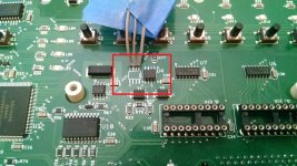
depending on the revision of your mainboard you may have 1 or 2 comm chips (your board is from '05 so it's likely a "revision B" with 1 chip). they're labelled U4 and U16, kindof in the middle of the board... if you have 2, replace them both. see below (I've pulled off U16):
IMG_20180315_202513381 - Copy.jpg

if you've got some soldering skills they're not hard to remove and swap. If you don't have a hot-air rework tool you can use a soldering iron (and a magnifier and a needle) and pull up 1 pin at a time - just use as low a heat as you can (like a 15watt iron with a very fine tip) or you might burn and/or pull up the pads.

If you don't feel comfortable doing it, send me a private message... I can do it for you but I do charge a reasonable fee. If the comm chip(s) is fine, you'd just have to pay return shipping and then probably send me the screenlogic ;)