Hayward Aqua Rite may be dead

Auburn02

Well-known member
Oct 8, 2019
320
Mobile, AL
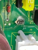
Noticed this morning my Hayward Aqua Rite 900 has no power, aka no LCD screen or LED light indicator. Did the basic troubleshooting, the board is getting 243V and the 20A fuse is good. I did find this piece on the control board marked “R18” that looks a little toasty. We’ve had some bad thunderstorms the last few days and I just replaced a TV that mysteriously went black (although that LED still comes on) so I’m thinking maybe we had some lightning coke close enough to cause some damage. The pump still works fine at least.

Anyone think of anything else I could test/try or should I consider my troubleshooting complete and order a new control board? I’m not sure what R18 actually is and if it would be worth replacing that individual component or just assume it’s a lost cause.
IMG_6415.jpegIMG_6411.jpegIMG_6414.jpeg
 
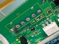
Well I decided to take a closer look and unless my eyes deceive me I see some other damage as well.

Now the question is where to buy? Searching these part numbers aren’t turning up any exact replacements yet. Finding an Aquarite GLX-PCB-RITE that lists compatible parts but not my specific board, but from reading the details and Q&A I gather this is what I need.


IMG_6416.jpegIMG_6418.jpegIMG_6420.jpeg
 

The board can likely be repaired.
Thanks for that link. Following along there - NO LIGHTS AND NO DISPLAY - I have landed on the rectifiers being blown and not a board issue at all - or may end up being both, but for sure I have 24V across the yellow wires coming off the transformer and I have zero (well, 0.1) volts across the red/black wires on each rectifier. I guess replacing those will be my first pass at this.

Tagging @C0d3Sp4c3 who seems to be one of the premier experts here to see if there is anything else I should be checking or if my interpretation of test results seems valid. Is it common/normal that both rectifiers would blow together? Do the markings I see on the green control board in my other pics also indicate a problem there?

Would be more than willing to send the control board off for repair, but now realizing the rectifiers may be bad (and not a part of the board obviously) I want to ensure I’ve done all the appropriate troubleshooting and not put all my eggs in one basket so to speak.

Thanks!

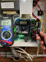
IMG_6427.jpegIMG_6426.jpegIMG_6425.jpeg
 
  • Like
Reactions: mknauss
@OP, the 20A fuse could have blown if either one of the bridge rects went dead short circuit. You are measuring 0V between the Blk and Red terminals because your VOM was set to read AC voltages instead of DC. Please place the selector switch on your voltmeter to read VDC when measuring DC voltages. Disconnect the Red wire from the pcb, you should read at least 22 Volts DC (unloaded) against the Blk wire and 30-32Vdc respectively when connected to the pcb. Remove the pcb and inspect for other possible damaged components or burnt marks.

The R18 is a 10 MegΩ resistor or a low impedance connection between the common ground point and Mains earth/Chassis. It has a key role in the correct grounding of electrical systems and or electronics. You can take care of it later. Try to troubleshoot and power up the pcb.

Edit: YT link added...
You have sw r1.59 and most likely the U13 went bad. You may want to watch this in preparation
or this
 

Attachments

  • AQR x'former + Rects.jpg
    AQR x'former + Rects.jpg
    55.7 KB · Views: 4
Last edited:
@OP, the 20A fuse could have blown if either one of the bridge rects went dead short circuit. You are measuring 0V between the Blk and Red terminals because your VOM was set to read AC voltages instead of DC. Please place the selector switch on your voltmeter to read VDC when measuring DC voltages. Disconnect the Red wire from the pcb, you should read at least 22 Volts DC (unloaded) against the Blk wire and 30-32Vdc respectively when connected to the pcb. Remove the pcb and inspect for other possible damaged components or burnt marks.
Thanks @C0d3Sp4c3 for catching that! The 20A fuse is not blown, but I will get out there to do further troubleshooting if this rain ever stops!
 
@OP, the 20A fuse could have blown if either one of the bridge rects went dead short circuit. You are measuring 0V between the Blk and Red terminals because your VOM was set to read AC voltages instead of DC. Please place the selector switch on your voltmeter to read VDC when measuring DC voltages. Disconnect the Red wire from the pcb, you should read at least 22 Volts DC (unloaded) against the Blk wire and 30-32Vdc respectively when connected to the pcb. Remove the pcb and inspect for other possible damaged components or burnt marks.

The R18 is a 10 MegΩ resistor or a low impedance connection between the common ground point and Mains earth/Chassis. It has a key role in the correct grounding of electrical systems and or electronics. You can take care of it later. Try to troubleshoot and power up the pcb.

Edit: YT link added...
You have sw r1.59 and most likely the U13 went bad. You may want to watch this in preparation
or this
First, I now find that both rectifiers are reading correctly. Thanks again.

Following the steps in the first video at the 2:57 mark, I measured exactly 24V at the left side of the R17 200ohm resister but only 3.5V at the other end, where I should see 22-23V.
IMG_6441.jpeg
IMG_6442.jpeg

Further downstream testing (pin 3 of the 5V regulator at 3:30) showed only 0.8V where I should see 5V; at this point I suspect the issue is in the R17 resistor.
IMG_6443.jpeg
I am capable of replacing the resistor, but did also go ahead and shoot out an email to B&L Enterprises for an estimated turnaround time to just send in the board, given the other visible evidence I documented above. Not sure which power rating that 200 ohm resistor should be but I suspect 1W based on dimensions, and there isn't exactly a Radio Shack on every corner anymore.

But then for one final test I disconnected the AC power and measured resistance across that resistor, reading 194.5 so pretty much within tolerance I'd imagine. Now I don't know what to think. Again.
IMG_6444.jpeg
 
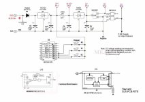
Apology for the delay. In the below circuit diagram, the current flows from left to right. Please be aware that the TP (Test Point) in the drwg is for reference only and does not correspond to the actual TP on the pcb. Based on your troubleshooting, the 20Vdc is missing at the other end of R17 (TP-2). Suggesting that there is a short circuit in the downstream components that is draining the current. Highly likely the U6 (5V regulator) went south. You have to desolder U6 and measure the resistance of TP-13 against the Negative post. There are a handful of yt videos on how to test a fixed voltage regulator. Or send out the pcb for repair if you're not comfortable.
There's a wealth of knowledge here >Hayward Aquarite SWG - Further Reading

GLX-PCB-RITE_OnBoard LVPS Schematic.jpg
 
Btw, I am not suggesting that replacing the U6 is a guaranteed fix. We don't know the extent of the damage caused by Lightning! But if it were me, I will remove the U6, test for short circuits, use an external 5Vdc at TP-13 and see what else goes up in smoke. Use your own judgment.
Here's the pin cfg of the 78M05 (D-Pak).

78M05 D-Pak.jpg
 
  • Like
Reactions: Auburn02
Huge help @C0d3Sp4c3 - I'm not against trial and error on my part, but the timing to do that is going to be an issue. I went ahead and ordered a replacement GLX-PCB-RITE (how are there so many specific Hayward model #s that ship with new systems, but only one replacement part??). I'll likely wait until it comes in, then swap out my board and either attempt to continue troubleshooting and do some soldering, or just send it out for repair. Either way it goes, hopefully end up with two functional boards and keep a spare on hand.
 
  • Like
Reactions: C0d3Sp4c3

Enjoying this content?

Support TFP with a donation.

Give Support
I hope you ordered the same OEM replacement pcb r1.59 for durability.
@C0d3Sp4c3 Well I would have preferred to but I was never able to source that, could only ever find “GLX-PCB-RITE” which appears to be touted as the proper replacement for all sorts of Aquarite part numbers. Did I miss it somewhere? I ordered it from Pool Supply World via EBay.
 
Last edited:
Ah, bummer - he said it appears the short is in the CPU, draining the primary voltage to 2.1V instead of 5.0 and he cannot source/repair that. Without having it in front of me I'm not sure which part on that circuit board is the CPU or if Hayward would sell it alone, but I'm not optimistic.

I'll install the new board I bought (which was labeled as R1.59 by the way, so that's good) and call it done.
 
Thread Status
Hello , This thread has been inactive for over 60 days. New postings here are unlikely to be seen or responded to by other members. For better visibility, consider Starting A New Thread.