Upon (thankful) feedback on this forum, I am replacing all of my CB's with GFCI's. I am replacing my 2-pole with a Pentair 20 AMP GCFI and all my 20 amp single CBs with 15 Amp GFCIs (Siemens QF115A SIEQF115A).
Thanks again for the help!
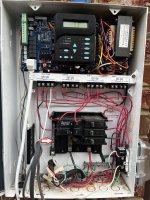
My pump is finally back to normal and running - now to make it safer.
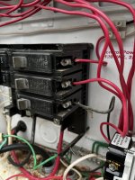
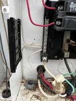
I'd like to get confirmation that the pig tail should be attached to what I believe is the neutral bar (red arrow in picture). I also assume that the lack of a neutral wire for the new CBs does not matter. I will just wire the hots and attach the pig tail to the neutral bar labeled in the picture.Thanks again for the help!
My pump is finally back to normal and running - now to make it safer.