IntelliPh Board Burned

That motor is DC. Just be sure your power supply is, too.
Thanks for that. Saved the motor. :)
I like the controller and all the niceties it provides
Me too.
We think the connector burn might have something to do with corrosion building up on the pins. It's certainly possible. That would increase resistance and the problem grows from there. If that's true, the other pins, through which the communication signals travel, could also be subject to this same problem. But instead of burning up (the COMM buss doesn't carry that kind of current), maybe it just loses comm's once in a while? Just a theory. But the same possible solution would work for all the pins, and that is to coat them with a good protective conductive grease, that both protects the pins and enhances conductivity. I haven't done so myself, but plan to before long. Can't hurt. I'll coat the pins inside my IpH, but also the pins that connect to my automation controller. Any connection, really, that is subject to the "harsh environment" of a pool equipment pad: salty, acidic air drifting around during both extreme heat and cold weather.
Oh this is fascinating. Can you link to the kind of grease you are suggesting? And you talking about the isolated connector pins, yes? Like the ones on the male side on the 4 pin DIN connectors?
 
Is your IC power center connected to a relay in the IntelliConnect? It's not supposed to wired that way but some are.
No sir. The IC Power Center and IntelliFlow pump are wired on a dedicated circuit to their own breaker as required. That breaker isn't a GFCI because Pentair's approved breaker is a very specific Siemens model. My box is Eaton, and the Eaton GFI breaker we tried tripped constantly, so we went with a standard breaker.
 
  • Like
Reactions: guinness
@Dirk I not sure I buy the corrosion argument now that I have this board on the bench with a meter. My hunch is that this board is very badly built and your simple parallel wiring scheme before the board is the answer.

@ogdento, the 24v side of the connector is nice and brown on the inside. Between the red pins I get continuity at 0.2ohm. Between the black pins, same, with the top black pin toasty. Between the white pins, same 0.2ohm continuity. So these are all open to each other as they should be for a parallel power circuit / data bus tap. And from here it just gets weird...

The green pins have no continuity to one another. I assume that's due to the damage to the board, as RS-232 is a very simple bus allowing parallel taps, so an intentional disconnect or serial connection through ICs shouldn't be required here. I mean maybe the iPH conditionally cuts the RS-232 bus to the IC40 to turn it off when dispensing, but I doubt that. It would be easier to send an "off" command, followed by an "on" command over the bus.

I might expect some continuity between the green and white pins, but at very high resistance. Nope! Bottom green pin is 1.5ohm to both white pins. And top green pin is disconnected from white pins, just like it is disconnected from the bottom green pin.

Most troubling is 05.-1.5ohm resistance between both black pins and (both white pins and the bottom green pin). Shouldn't this board simply be tapping the COMM bus, not providing power to it? If I understand how this works (I probably don't), I'm surprised all my other equipment isn't fried.
 

Attachments

  • toasty pin.jpg
    toasty pin.jpg
    39.4 KB · Views: 5
The green pins have no continuity to one another. I assume that's due to the damage to the board, as RS-232 is a very simple bus allowing parallel taps, so an intentional disconnect or serial connection through ICs shouldn't be required here. I mean maybe the iPH conditionally cuts the RS-232 bus to the IC40 to turn it off when dispensing, but I doubt that. It would be easier to send an "off" command, followed by an "on" command over the bus.
I can't help with the continuity aspect, but here's what happens normally (if I'm remembering @ogdento correctly).

Back to your original pic, the white box to the left of your large red circle is a small relay. That relay sits on the COMM bus (the green and white wires). When the IpH gets ready to dispense, it opens the relay and severs COMMs between the automation controller and the IntelliChlor. It then sends a command to the IntelliChlor to set its chlorine output to zero. Then dispenses. Upon completion the IpH restores the IC's output setting, and then closes the little relay and restores COMMs between controller and IC. This is how the IpH is able to turn the IC on and off quickly without the IC having to repeat its five-minute start up process each time acid is dispensed. (How'd I do, Tom?)

My guess is, the IpH both sets the IC to zero and severs the COMMs so that the controller doesn't get confused about the IC suddenly going to zero. The controller just maintains the IC's setting until COMMs are restored, otherwise if the user is looking at the IC interface on the controller, he would see it go to zero, then after a minute watch it go back to the correct number.

I also vaguely remember something about a several minute delay when Pentair automation controllers get or change settings, so perhaps severing the bus keeps that delay from squirreling up the works. Not sure.

What's not clear is why the controller doesn't present a COMMs error while the COMMs are severed. And maybe it does and we just don't notice, or we sometimes notice (like that's what I saw this morning)? I doubt it. It's possible the controller waits some period of time before it reports a COMM error, to cover for this scenario, or possibly to cover for the odd COMM error here and there, so it doesn't flood the user with every minor COMM snafu. Again, just guessing. Perhaps @ogdento can ponder that.
 
Oh this is fascinating. Can you link to the kind of grease you are suggesting? And you talking about the isolated connector pins, yes? Like the ones on the male side on the 4 pin DIN connectors?
I'm talking about any and all contact points of any and all connectors, inside and out. Whatever you can get to without too much trouble. Anything that can corrode from air contact.

When I used to live at the beach, my landline phones were always crackling. I finally figured out it was salt air corrosion on the little pins in the phone jack that plugs into the wall plate. Replacing cords and wall plates solved the problem. That's where I derived the theory of corroded pins and added resistance and COMM problems. But replacing Pentair cords and plugs and jacks is prohibitively expensive, and the resulting issues from corrosion can not only be very expensive, but can adversely affect your pool's operation. So yah, it's just a theory, but a sound one I believe. It might explain why some IpH owners have no problems, ever, others have severe problems, and some get problems only after many years (I'm the last two).

Pentair claims it only happens to IC60s (which draw the most current), but mine is an IC40 and several others here with IC40s had the same issue (sound familiar?).

Besides, if I'm wrong, so what. You lubed some connectors and maybe helped them work a little better.

Now the reason I haven't done mine yet is because I'm stuck picking out the right stuff. So I can't answer that question yet. I see many types on Amazon, but I'm not clear on which is best. I'm also worried about using one that so enhances conductivity that a sloppy application might span two pins and create a short! My guess is that is not how the stuff works, but I'm not dead sure of that and have yet to get around to gambling on that point. But feel free to and let me know how it goes!! :ROFLMAO:
 
Last edited:
OK @Dirk! Now we're cooking with gas!

If that relay cuts the COMM bus, that explains why my green pins have no continuity. My relay is charred on one side. I'm betting it's stuck open.

As I understand it, an RS-232 bus is deadly simple. Devices broadcast messages, and others observe them. Every once in a while the IC screams out its current status. The automation system wouldn't notice it coming and going from the bus unless 1) automation hadn't heard the IC broadcast a message in a while or 2) automation broadcast a command intended for the IC and didn't receive a response. Pentair does have a proprietary message protocol, and it could do more complicated things on top of the basic bus signaling, but I've not seen indication of anything fancy enough to notice a device going missing for a short period of time.

And you inspired me to try and control my IC40 from my iConnect. Commands are failing, despite the iPH being completely removed from the picture. Perhaps the iPH did damage the IC40's circuitry. My iFlow pump is receiving commands just fine, but it was connected to the bus upstream of the iPH.
 
  • Like
Reactions: Dirk
Ah, I think you're on to something regarding the IC only sending updates periodically. That makes sense, and jives with the notion that there is a delay when settings are altered by the user. They take a while to go into effect, I've read here, and maybe that's because the commands get queued and after a few minutes get sent "with the rest of the outgoing mail." Otherwise you'd have a dozen devices all trying to shout through the buss all the time at the same time.

Truthfully, I know just enough about this stuff to be dangerous!

As I mentioned, we've seen that part of the board fried before, the relay and the adjoining little resistors. We've seen that with the melted connector. But we don't yet have any ideas what causes that, or why not all of us have had that relay melt (mine didn't). One guy thinks he had a power surge, which could both melt those parts and finish off the already-taxed connector. But we're only dealing with a little data, what we can gather from about half a dozen instances of this problem, each one with their own symptoms.

What we can agree on is that the board is basically under-engineered. Thanks to some bean counters no doubt. That's why some of us have just abandoned the IpH controller and just used pool automation relays to run the IpH pump.
 
Last edited:
I not sure I buy the corrosion argument
Another data point: some times the red pins burn, other times it's the black pins. Sometimes both. That's why I'm leaning toward the corrosion factor. Something sets off one or the other sets of pins, and sometimes both. It could be a manufacturing defect: crummy metal pins tinned with something conductive but equally crummy. Already rough and pitted that would be conducive to corrosion. So one pin just happens to be worse than the next one, and gets the failure started. Or a combination of cheap pins plus corrosion. Maybe some IpH owners have better surrounding air conditions, or got a better set of pins, etc. It's something that's inconsistent from unit to unit.
 
Last edited:
Otherwise you'd have a dozen devices all trying to shout through the buss all the time at the same time.
Yes, Pentair comms are done over a RS-485 half duplex connection where the controller (IntelliConnect in this case) can query each device (with a unique id) like the IntelliChlor for status or to issue it a command. It then switches to receive mode to listen for the response and the addressed device transmits a reply. That way it can avoid collisions since only one device is transmitting at a time and the controller orchestrates that communication.
 
Last edited:

Enjoying this content?

Support TFP with a donation.

Give Support
hey guys, the 44-pin chip labelled u3 in the top right red circle is the micro-controller... i can't tell if other parts blew up and just burned "onto it", or if the micro-controller itself is burned. but i tend to agree with Dirk that the board is toast :( if the micro is okay you might be able to cobble the board back together but it would take some effort - probably not worth it!
It looks like this was a "dominos" failure. A big current surge took out the relay. The contacts are rated 1 amp continuous, 2 max. It's double pole, so maybe they're ganged. It's not a very robust part.

Then the next thing to go looks like a relay driver and the coil clamp diodes. So the power side of the relay must have shorted to the coil.

I found a picture of a different IntelliPh board that was clear enough to see the processor part number: 16F1939. The burned pins are GPIO either RE7 or RB3. Hard to tell. Doesn't matter. After the relay driver was a lump of carbon, the high current was shorted back to these. They're for low current signals, so pffft, the processor was gone.

That's a pretty spectacular failure path. Designing a circuit where no fuse blows before all that's complete is an art.

Yes I'd agree be extremely suspicious of that motor. The current surge must have been big. Something like 6 amps or more would make sense. A short or even a small freak lightning hit might do it, though the damage seems too localized. And you guys have shown a long history of excessive current-related failures. Lightning doesn't strike by brand and model number :)
 
Last edited:
Pentair comms are done over a RS-485 half duplex connection
Right! No idea why I had RS-232 on the brain yesterday... dreaming of modems and serial mice I guess.
It looks like this was a "dominos" failure. A big current surge took out the relay. The contacts are rated 1 amp continuous, 2 max. It's double pole, so maybe they're ganged. It's not a very robust part.

Then the next thing to go looks like a relay driver and the coil clamp diodes. So the power side of the relay must have shorted to the coil.
Agreed. The 24v power side does seem continuous to the COMM bus side of the connector now.

Couldn't get to the motor testing today because we had a nasty storm. But after I cleaned all the leaves out of the pool, I did notice I couldn't adjust the IC40 output from the Pentair Home app. The iConnect seemed to be getting some communication from the IC40: accurate water temp of 60F, inaccurate salt level of 0. I hope the IC40 is OK. The More Button diagnostic mode reports no issues. I'm not aware of its board being serviceable.

But I did decide to quickly check the IC Power Center. Another burned board...

power center.jpg
The 10amp fuse is fine of course. I assume it only protects the 24v side of things, not from excessive current flowing in from other devices on the COMM lines.
 
Designing a circuit where no fuse blows before all that's complete is an art.
They did blow. Clearly they just mislabeled the fuses as D2, D4, U5, U4, C13 and C14 (although those last two don't appear to have blown yet).

Back in the 80s, I used to fix RS-232 comm boards for Old DEC PDP systems - they used to blow the little 8pin DIP driver chips all the time. I remember I used to buy replacements for pennies and charge $100s of dollars for the repair. I swear, fuses would have been more expensive than those little ICs back then ;)
 
Right! No idea why I had RS-232 on the brain yesterday... dreaming of modems and serial mice I guess.

Agreed. The 24v power side does seem continuous to the COMM bus side of the connector now.

Couldn't get to the motor testing today because we had a nasty storm. But after I cleaned all the leaves out of the pool, I did notice I couldn't adjust the IC40 output from the Pentair Home app. The iConnect seemed to be getting some communication from the IC40: accurate water temp of 60F, inaccurate salt level of 0. I hope the IC40 is OK. The More Button diagnostic mode reports no issues. I'm not aware of its board being serviceable.

But I did decide to quickly check the IC Power Center. Another burned board...

View attachment 461240
The 10amp fuse is fine of course. I assume it only protects the 24v side of things, not from excessive current flowing in from other devices on the COMM lines.
Wow, two boards? Really does look like some sort of power spike event. Lightening or power company snafu. At least the mini-study we've been doing here has never seen that much damage and I don't recall instances of the damage spanning more than one board.

I have a Power Center, and I never considered what that 10amp fuse is actually protecting. I guess we know now what it doesn't protect. When my IpH connector fried, the IpH board and the Power Center board were fine. But I think I mentioned we have seen IpH board components fried when the connector was also fried. We think that instance was tied to a power surge event.

FWIW, my Power Center board doesn't look like that exactly. And I've seen multiple iterations of other boards and connectors, too. Pentair switches them up like that. Maybe that's them addressing these various engineering issues...
 
@Dirk, sorry for the delayed response. Pool was scheduled to be closed. That happened and I had to wait till this season. Now that I have a solution in place, it felt only right to share it with you, as you and the team here were so helpful in diagnosis.

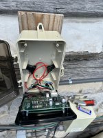
I've replaced the intelliChlor Power Center board as well as the intelliPH board. I've thoroughly checked all components. The intelliChlor Cell is fine. The intelliPH motor appears to be fine. I did contact the OEM of that motor, who told me that if it was continuous around 7ohms it was fine. Mine checked at 6ohms, which he confirmed in email was fine. My acid check valve seems to work, but does not appear to be in good shape, so I replaced it..

I connected an ammeter inline with the pump. Running acid freely into a bucket pulled max 0.8A. Adding on the old and new check valves saw the same draw. New check valve running into the plumbing, same again. The motor draw oscillates as it turns from 0.5 to 0.8A. I doesn't sound like it used to, so I suspect something isn't quite right with that motor. I'm going to keep an eye on it.

Two errors I now know I could have made:
  1. My acid pump is tied in on the heater loop plumbing. When the pool heater is bypassed, the acid pump would be pushing against no flow. The check valve design isn't made for this, there has to be suction on the output and pressure on the input. At some point, I might have created this situation and overloaded the motor.
  2. I left the plastic pump tube run for over 2 years without replacement. When the motor started making weird noises, I replaced the tube, which made the motor sound better, but never again as it originally was.

I believe one of of the above errors caused the motor to draw too much current. There is no overload prevention in the motor. And there appears to be no overload prevention for the motor on the iPH board.

I believe @generessler is right about the failure path. The pump pulled high amps on the 24v circuit. The intelliPH control board is powered at 48v but steps it down to 24v. There appears to be no over-current protection on the 24v side. Circuitry on the iPH board burned back from the motor. I believe that the comm bus and 48v power bus were shorted to one another when one of the chips burned. This went upstream to the comm bus circuitry on the intelliChlor board, burning out the comm chip only. Thus the intelliChlor continued to work, but no longer communicate with automation.

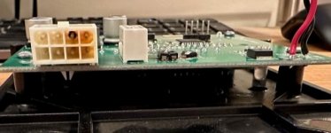
I also want to be cautious. The other threads you linked me to show very good reasons to believe that an intelliChlor can draw more than its rated current, and burn out the iPH board pins. I had pin burning. So I've added two inline fuses to the connecting wires:
  1. 1A inline fuse on the iPH motor.
  2. 7.5A inline fuse on the iChlor power connector.
Everything seems to work fine now. I'll report back to this group if I experience future issues. Pictures of the fuse arrangement attached.
 

Attachments

  • IMG_3733.jpeg
    IMG_3733.jpeg
    708.3 KB · Views: 8
  • IMG_3734.jpeg
    IMG_3734.jpeg
    498.3 KB · Views: 8
Last edited:
Thanks for the new data. Interesting use of the fuses, but I'm not convinced that will solve the problem, or at least one of the problems. Which is that the white four-conductor connector is not rated to handle the current the IC draws. A fuse that would allow the IC to function normally will not protect that connector, it'll still melt and eventually fail.

The fuse might help prevent some of the other failures you incurred, sure, so it is probalby good insurance. To solve for the connector melting, we've been bypassing it. If I didn't already share how we do that, I can if you're interested.
 
Are you suggesting that the white connector is not rated for the 7.3A it claims on the product label? My solution will break the connection if it draws 7.5A.

But if the connector can't handle 7.3A, that's super interesting. I assume you are just bypassing it on the red and black wires only? I could easily keep my 7.5A fuse for safety and still do that.
Exactly. You could combine our work-around with yours and be that much better off.

My theory is that the connector is mostly fine and adequate as is. But the metal pins are of inferior quality and when they start to corrode, due to outdoor elements or slightly misfitting, they add a bit of resistance. This results in heat, which encourages the corrosion, and then it cascades until there is enough heat to melt the connector and fry the pins until they disconnect. Something like that.

But you can't just bypass the red and black, because the board needs the red and black, too. You bridge the reds and blacks to create a better primary path, but maintain the connection to the board. I've offered these drawings, because I like solder, but you could do the same with wire nuts or Wagos. I fixed my own board before I thought of this simpler solution, by removing the connector and soldering directly on the board, but it was ugly (here, you might find other info in that thread interesting). Others here have used their own version of these with success.

Preemptive fix. This has the advantage of maintaining the function of the connector. I had envisioned some sort of insulator around the soldered joints, maybe hot glue or silicon or even electrical tape. Or cut the wires and use heat-shrink:
IntellipH-Mod-1.jpg
If the connector is already badly fried:
IntellipH-Mod-2.jpg

Or if the connector is suspect or just starting to go:
IntellipH-Mod-3.jpg
 
I did contact the OEM of that motor, who told me that if it was continuous around 7ohms it was fine. Mine checked at 6ohms, which he confirmed in email was fine. My acid check valve seems to work, but does not appear to be in good shape, so I replaced it..

I connected an ammeter to inline with the pump. Running acid freely into a bucket pulled max 0.8ohm. Adding on the old and new check valves saw the same draw. New check valve running into the plumbing, same again. The motor draw oscillates as it turns from 0.5 to 0.8ohm. I doesn't sound like it used to, so I suspect something isn't quite right with that motor. I'm going to keep an eye on it.

I think you mean amps, not ohms.
 

Enjoying this content?

Support TFP with a donation.

Give Support
Thread Status
Hello , This thread has been inactive for over 60 days. New postings here are unlikely to be seen or responded to by other members. For better visibility, consider Starting A New Thread.