
When we leave for several days, I've always turned off the pool pump and heater to my indoor Endless Pool, because if there were to be a leak in the circulation system, the damage could be substantial. Of course, the downside has been some episodes of bad-water quality upon returning.
I would like to be able to leave the circulation system on when gone, providing I am able to turn off the circulation system remotely if I were to detect leaks (using wifi leak detectors and cameras).
Ideally, the simplest way to do this would be a smart-plug to insert in the pump`s power-cord receptacle -- when power to the pump is disconnected, both the pump and the electric heater turn off.
However, as far as I know there are no smart plugs rated for 20 amps; the pump is on a 20-amp circuit. The pump is rated for about 13 amps, but it draws more when starting up; so, a smart plug isn’t a viable solution.
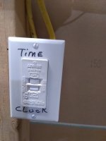
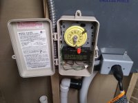
My pump and heater are controlled by an Intermatic T101P3 time switch. Although, I could replace the Intermatic with a wifi time switch, I’m hesitant to do so, because of potential problems with the control software (and possibly with the hardware). All I need to do is turn the system off; I do not need the other features of a digital time switch.
I recently discovered the availability of a wifi 30-amp circuit breaker (Smart Circuit Breaker by Martin Jerry, 30-Amp Circuit Breaker, Single Pole: Amazon.com: Tools & Home Improvement). If I were to wire this breaker between the time switch and the pump plug receptacle, then I could turn off power to pump and heater remotely. There is an existing GFCI breaker on the pump circuit (the wiring to that breaker runs out the side of the Intermatic time switch – through the conduit on the left side).
So, I am wondering if there is any electrical issue I am missing that would make wiring the 30-amp breaker between the timer/switch and pump on the 20-amp circuit a bad idea? For instance, would it interfere with the GFCI? Advice will be appreciated.
I would like to be able to leave the circulation system on when gone, providing I am able to turn off the circulation system remotely if I were to detect leaks (using wifi leak detectors and cameras).
Ideally, the simplest way to do this would be a smart-plug to insert in the pump`s power-cord receptacle -- when power to the pump is disconnected, both the pump and the electric heater turn off.
However, as far as I know there are no smart plugs rated for 20 amps; the pump is on a 20-amp circuit. The pump is rated for about 13 amps, but it draws more when starting up; so, a smart plug isn’t a viable solution.
My pump and heater are controlled by an Intermatic T101P3 time switch. Although, I could replace the Intermatic with a wifi time switch, I’m hesitant to do so, because of potential problems with the control software (and possibly with the hardware). All I need to do is turn the system off; I do not need the other features of a digital time switch.
I recently discovered the availability of a wifi 30-amp circuit breaker (Smart Circuit Breaker by Martin Jerry, 30-Amp Circuit Breaker, Single Pole: Amazon.com: Tools & Home Improvement). If I were to wire this breaker between the time switch and the pump plug receptacle, then I could turn off power to pump and heater remotely. There is an existing GFCI breaker on the pump circuit (the wiring to that breaker runs out the side of the Intermatic time switch – through the conduit on the left side).
So, I am wondering if there is any electrical issue I am missing that would make wiring the 30-amp breaker between the timer/switch and pump on the 20-amp circuit a bad idea? For instance, would it interfere with the GFCI? Advice will be appreciated.
Attachments
Last edited:
