- Jun 19, 2014
- 27
- Pool Size
- 20000
- Surface
- Plaster
- Chlorine
- Liquid Chlorine
- SWG Type
- Pentair Intellichlor IC-40
I hate to have to ask for help on this because I've read so many other posts about it, but I somehow still am getting it wrong.
After my old IC40 died, it seemed like a good time to get some automation options for the future, so I bought an EasyTouch 4PSC-IC40. The IC40 went right to work - I'd replaced one before. For the EasyTouch, before I changed anything, I spent a lot of time reading about it & -- from what I learned -- I knew wiring it likely would be a challenge, but I thought I could do it because -- at this point -- all I have to deal with is the SCG and the pump. No heater, no water features, etc. Seemed like that should make it easier.
My first surprise was when I discovered the underground PVC conduit (1/2" ID) from the main panel to the pump area contained only separate black, red, & green wires -- no white wire. So I pulled a new white wire ( THAT was a whole lot less fun than I wanted).
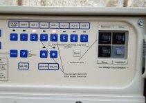
After mounting the EasyTouch (the easiest part), I tried principally following Pentair's instructions with notes I had made from other TFP posts. I quickly discovered that -- for me -- Pentair's having including Intellitouch info mixed with EasyTouch info got very confusing, so I scratched out the Intellitouch text and illustrations and I believe it was a bit clearer.
After doing the wiring, when I turned it all on, the lights above AUX2 & AUX 4 flashed ON and the small 3A breaker in the top panel tripped. So I've done something wrong, I just don't know what it is.
Here's how I intended it to be set up:
An existing 30A 240VAC breaker (non-GFCI) at main panel in garage supplies power (via Bk, R, W, & G wires) to connectors of ET subpanel.
I installed a 20A 240VAC GFCI breaker in the EasyTouch subpanel.
Using a R & a Bk jumper wire, I connected the two terminals of the 240VAC GFCI breaker in the ET subpanel to the two LINE terminals of the Filter Pump Relay.
I connected the Intelliflo 2 VST pump's power wires as follows: R & Bk directly to the two terminals of the 240VAC GFCI breaker in the ET subpanel; W to the white bar; & G to the ground bar.
From the SCG Transformer (wired for 240VAC), I connected its W & Y wires to the two LOAD terminals of the Filter Pump Relay.
Because I had on hand a 20A 120VAC GFCI outlet I needed to have mounted on the side of the ET box and I also had on hand a 20A 120VAC breaker (non-GFCI), I installed that breaker into the ET subpanel, then connected a (Bk) jumper wire from that breaker to the upper hot-side terminal on the GFCI Outlet and connected a W jumper wire from the upper neutral (white) side of the GFCI Outlet to the White bar.
To provide GFCI protection for the System Transformer, I left it wired for 120VAC and connected its Bk wire to the lower hot-side terminal on the GFCI Outlet and connected its purple wire to the lower neutral (white) side of the GFCI Outlet, so the System Transformer would receive GFCI-protected 120VAC power.
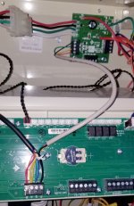
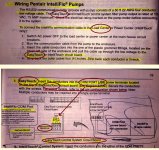
For the low-voltage wiring in the top section, I followed the directions as best I could. However, it required some interpretation because the SCG circuit board illustrated in the manual is different than the one that came mounted in my ET.
The manual references (& its illustrations show) a SCG circuit board with "COM1" marked on it and instructs that the R, G, Y, Bk wires should be connected between that COM1 and the "J20 COM Port" on the ET main circuit board (which is correctly marked). My ET came with its R, G, Y, Bk cable already connected to "JP2" on the SCG circuit board, so I've assumed that to be the referenced "COM 1" and just left it there.
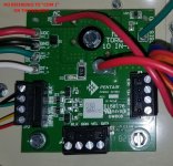
The last anomaly is the low voltage wiring for the IntelliFlo 2 VST pump. The manual references a 4-wire cable with R, G, Y, Bk wires. The cable for my pump contains 5 wires: R, Blue, Y, Bk, & W (I checked inside the pump and those colors correspond to the stamped color abbreviations on the pump itself). So I treated the Blue as a Green wire and just tied off the (now) extra white wire.
I've taken, annotated, and attached photos that may better clarify what I've tried to describe above.
I hope someone can tell me what I've done wrong and what I must do to make it all work as it should.
Thanks,
Paul
After my old IC40 died, it seemed like a good time to get some automation options for the future, so I bought an EasyTouch 4PSC-IC40. The IC40 went right to work - I'd replaced one before. For the EasyTouch, before I changed anything, I spent a lot of time reading about it & -- from what I learned -- I knew wiring it likely would be a challenge, but I thought I could do it because -- at this point -- all I have to deal with is the SCG and the pump. No heater, no water features, etc. Seemed like that should make it easier.
My first surprise was when I discovered the underground PVC conduit (1/2" ID) from the main panel to the pump area contained only separate black, red, & green wires -- no white wire. So I pulled a new white wire ( THAT was a whole lot less fun than I wanted).
After mounting the EasyTouch (the easiest part), I tried principally following Pentair's instructions with notes I had made from other TFP posts. I quickly discovered that -- for me -- Pentair's having including Intellitouch info mixed with EasyTouch info got very confusing, so I scratched out the Intellitouch text and illustrations and I believe it was a bit clearer.
After doing the wiring, when I turned it all on, the lights above AUX2 & AUX 4 flashed ON and the small 3A breaker in the top panel tripped. So I've done something wrong, I just don't know what it is.
Here's how I intended it to be set up:
An existing 30A 240VAC breaker (non-GFCI) at main panel in garage supplies power (via Bk, R, W, & G wires) to connectors of ET subpanel.
I installed a 20A 240VAC GFCI breaker in the EasyTouch subpanel.
Using a R & a Bk jumper wire, I connected the two terminals of the 240VAC GFCI breaker in the ET subpanel to the two LINE terminals of the Filter Pump Relay.
I connected the Intelliflo 2 VST pump's power wires as follows: R & Bk directly to the two terminals of the 240VAC GFCI breaker in the ET subpanel; W to the white bar; & G to the ground bar.
From the SCG Transformer (wired for 240VAC), I connected its W & Y wires to the two LOAD terminals of the Filter Pump Relay.
Because I had on hand a 20A 120VAC GFCI outlet I needed to have mounted on the side of the ET box and I also had on hand a 20A 120VAC breaker (non-GFCI), I installed that breaker into the ET subpanel, then connected a (Bk) jumper wire from that breaker to the upper hot-side terminal on the GFCI Outlet and connected a W jumper wire from the upper neutral (white) side of the GFCI Outlet to the White bar.
To provide GFCI protection for the System Transformer, I left it wired for 120VAC and connected its Bk wire to the lower hot-side terminal on the GFCI Outlet and connected its purple wire to the lower neutral (white) side of the GFCI Outlet, so the System Transformer would receive GFCI-protected 120VAC power.
For the low-voltage wiring in the top section, I followed the directions as best I could. However, it required some interpretation because the SCG circuit board illustrated in the manual is different than the one that came mounted in my ET.
The manual references (& its illustrations show) a SCG circuit board with "COM1" marked on it and instructs that the R, G, Y, Bk wires should be connected between that COM1 and the "J20 COM Port" on the ET main circuit board (which is correctly marked). My ET came with its R, G, Y, Bk cable already connected to "JP2" on the SCG circuit board, so I've assumed that to be the referenced "COM 1" and just left it there.
The last anomaly is the low voltage wiring for the IntelliFlo 2 VST pump. The manual references a 4-wire cable with R, G, Y, Bk wires. The cable for my pump contains 5 wires: R, Blue, Y, Bk, & W (I checked inside the pump and those colors correspond to the stamped color abbreviations on the pump itself). So I treated the Blue as a Green wire and just tied off the (now) extra white wire.
I've taken, annotated, and attached photos that may better clarify what I've tried to describe above.
I hope someone can tell me what I've done wrong and what I must do to make it all work as it should.
Thanks,
Paul