GFCI Trips after Poweroutage

You're missing the point. It's not the tub that needs the neutral, it's the GFI. Take a closer look at the breaker, or even better, RTFM. It's a little hard to tell from the photo what's going on with all the white wires, but there's another neutral terminal on the GFI, apart from the white pigtail. One of them is for the incoming neutral, the other goes to the load.

And you're not going to perform any meaningful test on the GFI with a VOM/DVM. It's too complicated (internally) for that.
Thank you I'll try that.
The challenge is that I redid the setup exactly how it was, the original installation.
 
You're missing the point. It's not the tub that needs the neutral, it's the GFI. Take a closer look at the breaker, or even better, RTFM. It's a little hard to tell from the photo what's going on with all the white wires, but there's another neutral terminal on the GFI, apart from the white pigtail. One of them is for the incoming neutral, the other goes to the load.

And you're not going to perform any meaningful test on the GFI with a VOM/DVM. It's too complicated (internally) for that.
This is the original setup that has worked well until the recent power outage:
It's a 3-wire setup and as you pointed out the white wire from the hot tub is not connect on the hot tub side
 

Attachments

  • Original GFCI - 2010 Sundance Optima.jpg
    Original GFCI - 2010 Sundance Optima.jpg
    251.8 KB · Views: 12
Still not making Any progress (slightly frustrated and pride being to fix something doesn't let me call an electrician😁).
Here is my GFCI breaker box setup - took a pic before exchanging the old GFCI breaker with this new one.
It still trips.
I can hear the circulation pump come on for 1 second and then it trips.
My thought is that power from the breaker panel in the garage supplies power to this breaker, there shouldn't be an issue there.

One more question: how do I test, with a multimeter, if the GFCI is faulty ?
I showed 122 on both the red and black wires (from the main breaker box)
What am I missing between the GFCI breaker and the hot tub?

Thank you all for your help.👍👍

A GFCI does not worry about the voltage, it worries about the difference in voltage (or more accurately current). In simplistic terms it measures the current going out of the breaker, and the current coming back in. If there is a difference in these, it means that current is going somewhere else, such as through a human. If this happens it trips. It does this by putting the wires through an induction coil. IF a voltage is induced in the coil that means there is a delta and it trips.

Note that it will trip as long as there is a difference. So if somehow you were returning MORE current than was going out, that would trip it as well.

The upshot being, you really cannot test it. Either the mechanism is working, or something is worn out or loose and it has a nuisance trip.

If you hook everything up, but remove the circ pump from the board in the hot tub, does it still trip?
 
  • Like
Reactions: Mdragger88
You're missing the point. It's not the tub that needs the neutral, it's the GFI.
Nobody is missing the point but you. No time to explain, I'll leave that between you and google, but this is false.

It's a 3-wire setup and as you pointed out the white wire from the hot tub is not connect on the hot tub side
👍
As I said before, if you disconnect the main power wires at the spa (2 blue) and it still trips it is the breaker. I cannot help you if you do not try what I suggest and respond. There is 1 person in this conversation who repairs these for a living. Who do you want to listen to?
This is my last attempt to help you.
 
The white “pigtail” wire on a GFCI circuit breaker serves two functions.

It completes the connection to the panel neutral bar for the neutral load conductor and also completes the power supply circuit for the electronics.

This means that even in installations where there is no load neutral conductor, the white pigtail wire must still be connected to the neutral bar in the load center or panelboard in order for the electronic ground-fault protection circuit to function.


Enjoying this content?

Support TFP with a donation.

Give Support
Correct, which is why I can't figure out why buddy's trying to pick a fight over this. The GFI neutral needs to be connected to the panel regardless of whether there's a load neutral connection.

Incidentally, different style of breaker than the Square D/Schneider I just installed - this one has the load neutral screw up top and easier to confuse with the pigtail.
 
You're missing the point. It's not the tub that needs the neutral, it's the GFI. Take a closer look at the breaker, or even better, RTFM. It's a little hard to tell from the photo what's going on with all the white wires, but there's another neutral terminal on the GFI, apart from the white pigtail. One of them is for the incoming neutral, the other goes to the load.
There is no terminal for an "Incoming" neutral.

The pigtail is the "Incoming" or "line" neutral.

The white pigtail is connected, so the GFCI's need for a neutral is satisfied.

The neutral terminal is for the Load Neutral and it is not used for this application since the load is 240 only.
 
Shut off all power and disconnect the power wires from the breaker.

Check for continuity from each hot to ground.

Disconnect things until the continuity goes away.

Disconnect the appliances, like the heater, pump etc. from power and test for continuity to ground from the power terminals.

Note: I recommend that you have a qualified expert help you with this since it is a safety issue.

Do not do anything unless you are 100% sure that you can do it safely.
 
Last edited:
Shut off power at the main breaker panel and at the disconnect/subpanel.

Verify no voltage at the subpanel/disconnect.

Test for continuity/resistance from each hot wire to ground.

The reading should be O.L, which means Open Line.

If there is a reading for resistance (Ohms), then you have a path for current to leak to ground.

The ground fault might be on the other side of a relay, so you will probably need to disconnect each appliance and test for resistance/continuity from the power/hot terminals to ground.

Hot to ground should read O.L.

If there is a reading in ohms, then you have a ground fault.

Note: If the tub used a neutral, it would be more complicated because the neutral is a grounded conductor.

An appliance with a neutral can read conductivity from hot to ground through the appliance, through the neutral and to ground in the main panel unless you properly isolate the wires.

The neutral is called the “grounded conductor” because at the service panel, it is bonded to the ground conductor.
 
All three wires pass through the toroidal ring, which will induce a current if the current in the three wires does not exactly cancel out.

If the imbalance is 4 to 6 milliamps, the breaker trips.

So, the pigtail carries the neutral current and it allows the internal circuitry to be powered to perform the necessary safety function.

1737077030850.png
 
Last edited:
The true purpose of the GFCI is to “sense” when there is a current leakage between a power source and a grounded surface.

The GFCI is designed to determine that there is a difference in the amount of electricity making its way into the circuit, versus some that might be “flowing out”.

In this situation, a small amount of current, as little as 4 or 5 milliamps, is detected by the “sensing coil” built into the GFCI device, and the unit “shuts” off the circuit, stopping the flow.

This reaction occurs less than one-tenth a second.

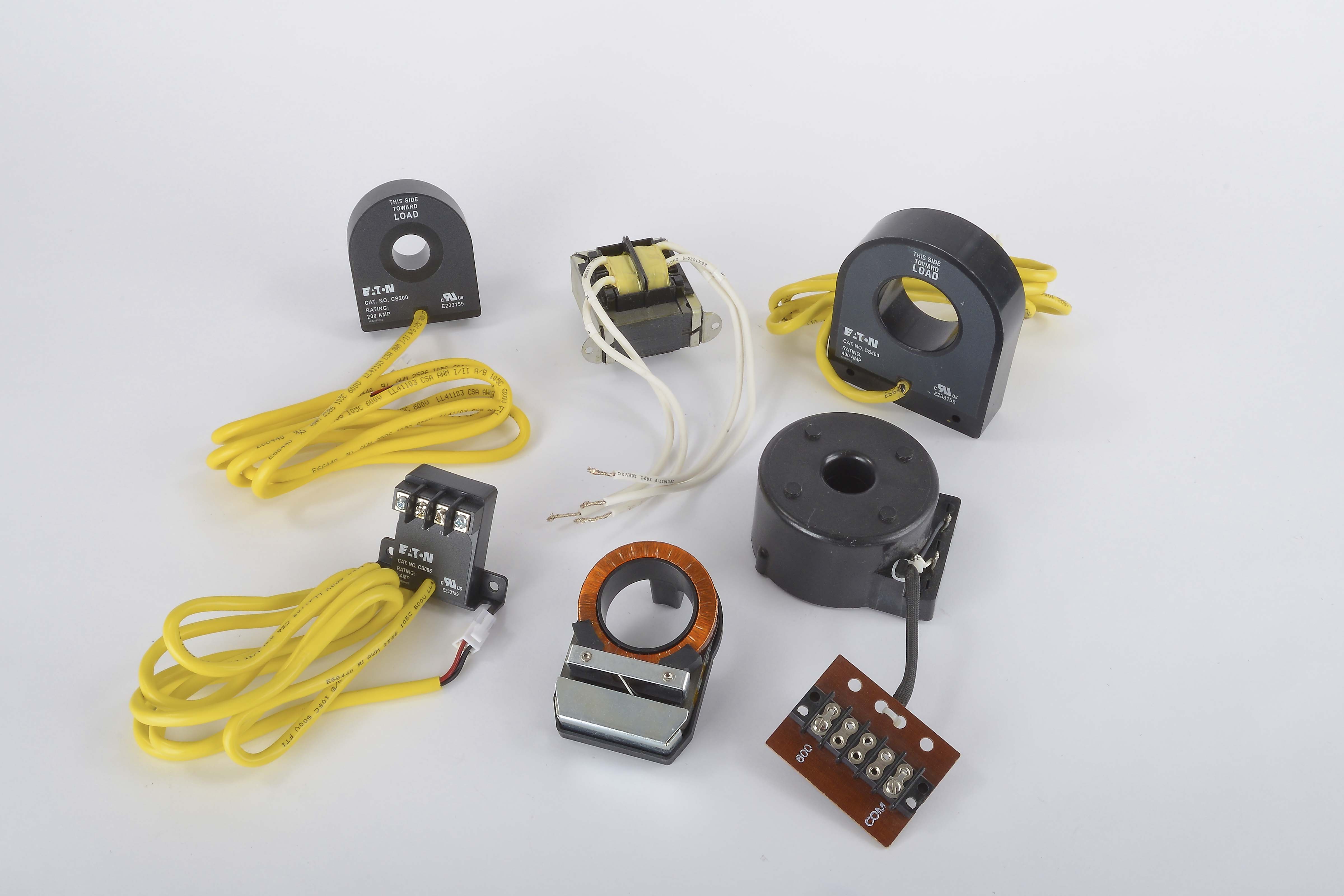
The product that “senses” this leakage, is simply called a “sensing coil”.

Typically made up of a high nickel ring core, in a case shaped like a donut that can be as small as a dime in diameter, wound with copper magnet wire, then sealed in a potted case, it is the critical part of a GFCI.


1737077416327.png
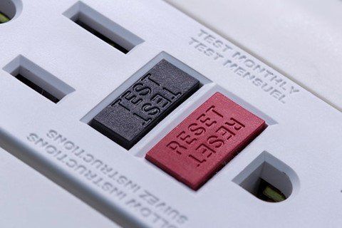
How does GFCI protection work?

GFCI’s use an ingeniously simple mechanism for detecting stray currents.

They utilize a doughnut-shaped iron ring inductor called a toroidal coil to help contain magnetic fields.

Both the hot (supply) and neutral (return) legs of the circuit are coiled around the sides of the ring.

Along with these, a secondary coil is used for a sensor that would naturally pick up induction through any magnetic fields created by current in the live circuit.

With this set-up, as long as the hot and neutral currents are equal, their magnetic fields cancel one another, and no current is induced into the sensor coil.

If they become imbalanced, which would indicate a ground fault, a current is induced into the sensor which in turn activates a relay to open internal contacts in the receptacle, thus breaking the circuit and stopping current flow.


Enjoying this content?

Support TFP with a donation.

Give Support
Thread Status
Hello , This thread has been inactive for over 60 days. New postings here are unlikely to be seen or responded to by other members. For better visibility, consider Starting A New Thread.