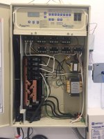
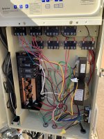
Pentair La01n Booster Pump-anything I'm missing?

Dec 8, 2017
9
keller, texas
FIrst, love this forum, so many knowledgable and helpful folks which has allowed me to troubleshoot and fix several items on my pool over the years.
Based on researching similar posts, I think I know my situation, but posting here just in case I'm missing something;

The booster pump will not turn on, no humming or clicking, nothing at all.
-confirmed 240v at the control panel breaker running the booster pump (same breaker runs the booster pump and filter pump, and filter pump is running fine).
-confirmed 240v at the back of the booster pump (with power 'on' and cleaner turned 'on', used multi-meter to check L1 and L2)
-shaft at the back of the booster pump turns freely and easily by hand
-replaced capacitor at the top of the pump (first thing I did, although now I know the original capacitor was fine).
-pump is about 4 years old

Anything I'm missing?
Thanks in advance!
 
Confirm that you tested 240V with your probes on L1 and L2. Not between L1 or L2 and GROUND.

4 years is a short pump life.
 
  • Like
Reactions: wireform
Confirm that you tested 240V with your probes on L1 and L2. Not between L1 or L2 and GROUND.

4 years is a short pump life.
Confirmed, checked l1 and l2
Are you saying you have a control panel or just a circuit breaker panel? please fill us in a bit vague.
next to the pool equipment is the control panel, easy touch..top portion is the lcd screen and control buttons and the bottom 2/3 is all of the wiring and breakers. That’s where I checked the breaker, but the same breaker runs the filter pump, which is working, so I guess I didn’t need to check it afterall.
 
next to the pool equipment is the control panel, easy touch.
From the breaker, the power should go to the Filter Relay Line Terminals and then from the Filter Relay Load Terminals to the Cleaner Booster Pump Relay Line Terminals and then the booster is connected to the Booster Pump Load Terminals.

Are you getting 240 volts when testing line to line at the pump terminals and at the Booster Relay Load Terminals?
Easy 2.jpgEasy Touch.JPG
 
From the breaker, the power should go to the Filter Relay Line Terminals and then from the Filter Relay Load Terminals to the Cleaner Booster Pump Relay Line Terminals and then the booster is connected to the Booster Pump Load Terminals.

Are you getting 240 volts when testing line to line at the pump terminals and at the Booster Relay Load Terminals?
View attachment 621013View attachment 621014
Thanks! I’ll check all this tomorrow and post pictures of where I checked.
 
As you can see in this picture, the Filter Pump Relay gets power from the breaker.

The Booster Pump Relay usually gets power from the Filter Pump Relay so that the Booster is interlocked with the Filter Pump.

You can interlock in settings so it does not always need to be interlocked in the wiring.

Most likely, you have lost one leg of the power supply.

The red dots are the Line Terminals and the Blue Dots are the Load Terminals.

Test the voltage from red dot to red dot and blue dot to blue dot on each relay.

1733943803194.png

1733944040240.png
 
  • Like
Reactions: wireform

Enjoying this content?

Support TFP with a donation.

Give Support
TFP is a registered 501(c)3 non-profit that is maintained by user donations.

All of our content is free of advertisements.

Please consider donating at:

 
Thread Status
Hello , This thread has been inactive for over 60 days. New postings here are unlikely to be seen or responded to by other members. For better visibility, consider Starting A New Thread.