I’m having this exact same issue. Pump’s turn off, but the SWG stays on and blinks red/green continuously. I don’t see anywhere within the config app or ScreenLogic app to set up a schedule for the SWG. Any recommendations from you smart people?

Pentair Intellichlor IC40 lights stay on with pump off
- Thread starter KMorg
- Start date
You are using an out of date browser. It may not display this or other websites correctly.
You should upgrade or use an alternative browser.
You should upgrade or use an alternative browser.


- May 3, 2014
- 62,774
- Pool Size
- 6000
- Surface
- Fiberglass
- Chlorine
- Salt Water Generator
- SWG Type
- Pentair Intellichlor IC-40
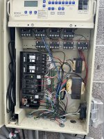
The SWCG power is wired incorrectly.
The power must come from the LOAD side of the Filter/Pump relay.
Have this fixed soon. There is a threat of the SWCG exploding if the flow switch fails.
The power must come from the LOAD side of the Filter/Pump relay.
Have this fixed soon. There is a threat of the SWCG exploding if the flow switch fails.
Whoa, that’s scary. I’ll get it fixed right away. If I recall correctly, it didn’t do this at all last year and none of the wiring has been changed. Is it possible it’s a setting issue?
- May 3, 2014
- 62,774
- Pool Size
- 6000
- Surface
- Fiberglass
- Chlorine
- Salt Water Generator
- SWG Type
- Pentair Intellichlor IC-40
K,
The fix could be very simple...
Show us a couple of pics of your Pump/Filter relay inside your EasyTouch.. So we can see the wiring...
Thanks,
Jim R.
The fix could be very simple...
Show us a couple of pics of your Pump/Filter relay inside your EasyTouch.. So we can see the wiring...
Thanks,
Jim R.


K,
Well, it won't be as easy as it could have been...
1. Read the warning that is on the SWCG transformer.. (The big one...) If this is a new pool, you might want to ask your Pool builder why it is not wired correctly.
2. The SWCG transformer can be wired for 120 volts AC. or 240 volts AC.. Because all the wires are bunched together, it is impossible for me to tell how it is wired.
3. Before we can move on, I need to know if you want to try to rewire this, or do you intend to have someone else come in and rewire it.
4. If you want to try, then I need to know where the 4 Transformer wires go... They are Yellow, Violet, Black, and White.. These wires come from the big transformer.. Don't confuse them with the same color wires that come from the System Transformer (The small one..)
Thanks,
Jim R.
Ahultin
Bronze Supporter
- Aug 19, 2021
- 1,607
- Pool Size
- 17700
- Surface
- Plaster
- Chlorine
- Salt Water Generator
- SWG Type
- Pentair Intellichlor IC-40
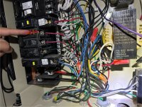
Swg appears to be wired to relay 2 fed 120v off of the single pole gfci breaker using blue for hot. Open the low voltage compartment and confirm the relay l2 lv is connected to the filter pump header on the easytouch control board.
Hey Jim, thanks so much for the reply. I’d love to rewire things myself. I was the owner/builder for my pool and subbed out all of the work, including the electrical. The guy was very sloppy in a lot his work, so I’m not terribly surprised to learn that he didn’t do it correctly. I could call him back out to fix it, but I honestly don’t trust him much at this point. I hadn’t seen the very obvious warning sign about wiring it to the pump until I opened it up to dig into this. It sounds like I’m very fortunate that there hasn’t been substantial damage.K,
Well, it won't be as easy as it could have been...
1. Read the warning that is on the SWCG transformer.. (The big one...) If this is a new pool, you might want to ask your Pool builder why it is not wired correctly.
2. The SWCG transformer can be wired for 120 volts AC. or 240 volts AC.. Because all the wires are bunched together, it is impossible for me to tell how it is wired.
3. Before we can move on, I need to know if you want to try to rewire this, or do you intend to have someone else come in and rewire it.
4. If you want to try, then I need to know where the 4 Transformer wires go... They are Yellow, Violet, Black, and White.. These wires come from the big transformer.. Don't confuse them with the same color wires that come from the System Transformer (The small one..)
Thanks,
Jim R.
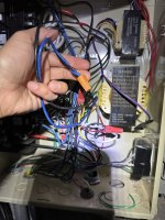
I’m fairly comfortable with electrical work, and would love your help. Pictures are attached.
Off of the SWG transformer there are 5 wires I see. Black, blue, yellow, white and green. Off of the main easy touch transformer I see 3 wires…black, violet, and yellow.
Could you confirm which one you need to see where they lead?
Here’s a few more pics to show greater detail. Also looks like it’s setup as 240v.
Attachments


K,
I have got things that I have to do today, so I won't be able to fully answer until late this afternoon.. But, here is how you want to end up... If not clear to you, please wait for more info..
Since the Violet and Black are wired nutted together, this means the Transformer is wired for 240 volts
240 volts has two hot leads, one called L1 and one called L2.. These are two separate 120 volts lines and between them you get 240 volts AC.
This means the Yellow lead from the larger transformer gets connected to L1 (120 volts)
And the White lead from the larger transformer gets connected to L2 (120 volts)
It does not matter which you call L1 or L2, it makes no difference...
The Pump/Filter relay, is located in the upper left of the panel.
We will call the left most connection screw Pin 1 (Line in), then 2 (Load out), 3 (Line in) and pin 4 (Load out) (See the diagram on the door)
Connect the Yellow wire to pin 2 of the relay
Connect the White wire to pin 4 of the relay
Connect pin 1 of the relay to L1.
Connect pin 3 of the relay to L2.
It does not matter where you get L1 and L2, but it is logical to just use the same breaker that is being used now. The two outputs of a 2-pole breaker are L1 and L2.
I would leave all the other wiring connected as it is now, as I have no clue what else that breaker is powering..
Once the SWCG transformer is connected to the load side of the Pump/Filter relay, the Cell will only work when in the Pool or Spa modes.
Thanks,
Jim R.
Last edited:
That all seems to make sense to me. Essentially, I need to get power from L1 (which can be any breaker) to Pin 1 which is line in for the filter pump. The second line in will positioned at Pin 3. Then the yellow and white wires from the SWG transformer should be connected to both load out screw pins which would be Pin 2 and 4. Does that sound about right?
The power to the SWG right now appears to come directly from the breakers that are marked red on the picture. They are wire nutted together with the white and yellow lines from SWG. So I should remove this white and yellow line from each respective wire nut and connect those to the respective Pin 2 and 4 on the relay. I could then run a new line from the same wire nut I just removed the white and yellow lines from, and connect those to Pin 1 and 3 to power the relay. If I’m correct, that all makes sense to me.
The part that I’m not clear on is the violet (purple) line coming from the main transformer. That is not connected to anything. You said the violet and black wires were wire nutted together, but it is a blue and black wire off of the SWG transformer that are wire nutted together. Just wanted to make sure I’m not missing something.
Also, thank you so much for your help! Can’t believe the amazing help you’re offering.
Attachments

K,The power to the SWG right now appears to come directly from the breakers that are marked red on the picture. They are wire nutted together with the white and yellow lines from SWG. So I should remove this white and yellow line from each respective wire nut and connect those to the respective Pin 2 and 4 on the relay. I could then run a new line from the same wire nut I just removed the white and yellow lines from, and connect those to Pin 1 and 3 to power the relay. If I’m correct, that all makes sense to me.
Correct..

Do not confuse the two transformers.. The small one is for system power and you should just leave it as it is... (Note.. the violet wire from the little transformer is not used when the little transformer is wired for 240 volts.. The end should be taped over or have wire nut just to cover it..
The big transformer is the only one you should be worried about..
Thanks,
Jim R.
Ahultin
Bronze Supporter
- Aug 19, 2021
- 1,607
- Pool Size
- 17700
- Surface
- Plaster
- Chlorine
- Salt Water Generator
- SWG Type
- Pentair Intellichlor IC-40
Keep in mind, unless I'm missing something @Jimrahbe , if you feed the filter pump relay off of anything other than the filter pump breaker you leave the possibility of the filter pump tripping the breaker which would remove flow but not remove power to the swg.I could then run a new line from the same wire nut I just removed the white and yellow lines from, and connect those to Pin 1 and 3 to power the relay. If I’m correct, that all makes sense to me.
A,
There are a number of things that could allow the cell to get AC power and for the pump not be running even if they are powered by the same breaker..
The system does not really even know if the pump is running.. It just assumes it is running...
Cell explosions are very rare, even when just the flow switch is used as the only safety device.. Routing the power through the Pump/Filter relay just adds a little extra protection.
For the cell to explode, the pump would have fail to run (for whatever reason) and the flow switch would have to fail in the closed position.. It is unlikely for both of these two things to happen at the same time.
It might be a little more worrisome if we were controlling a nuclear power plant, but that is not the case...
Thanks,
Jim R.
Last edited:
I’ll fly airplanes all day long, but nuclear power is beyond my level of expertise!  I’ll leave that to much more qualified individuals!
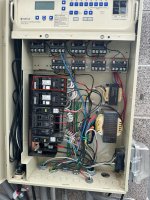
The breaker it’s currently set up on is heater breaker. The filter pump is on a 20amp breaker that’s marked in red on the pump. Any issue if I just connected pin 1/pin 3 to the 2 wires coming off of this 20amp breaker?
One other question I have is about the control board that the wire coming from the SWG is directly connected to. I get that the power is coming via the circuit breakers and transformer which I will correctly wire to power at the proper time. Do I need to change anything with the wiring if that control board?
Thanks guys!
I’ll leave that to much more qualified individuals! The breaker it’s currently set up on is heater breaker. The filter pump is on a 20amp breaker that’s marked in red on the pump. Any issue if I just connected pin 1/pin 3 to the 2 wires coming off of this 20amp breaker?
One other question I have is about the control board that the wire coming from the SWG is directly connected to. I get that the power is coming via the circuit breakers and transformer which I will correctly wire to power at the proper time. Do I need to change anything with the wiring if that control board?
Thanks guys!
Attachments
K,
If the SWCG worked before, the the control board (Surge card) is wired just fine,,,
Let's just do one thing at a time.
It does not matter where you get the 240 volts that you connect to Pins 1 and 3 of the Pump/Filter relay..
Once you get it all wired up, keep in mind that the cell will only get power when the system is in AUTO and in the Pool mode or the Spa mode.
Thanks,
Jim R.

K,
Looks good to me...
As a test... Go into the Service mode.. Wait about 30 seconds and all the lights on the cell should be off..
Put it back into Auto, wait a minute or so and everything should fire back up and the cell's lights will come back on.. You should see the cell's salt lights flashing as it goes through it start up routine.
Show me, are tell me what your schedules look like.
Thanks,
Jim R.
Thread Status
Hello , This thread has been inactive for over 60 days. New postings here are unlikely to be seen or responded to by other members. For better visibility, consider Starting A New Thread.