
Heat can be calculated by the formula V2/R or I2R or voltage x current.
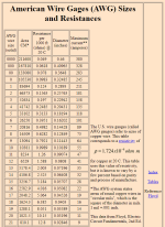
For example, the resistance of 1,000 feet of #8 AWG wire = 0.6282 ohms.
At 10 amps, the power (heat) = 102(0.6282) = 62.82 watts.
That heat causes the wires and switches to heat up beyond the ambient and that causes the heat to begin to be lost due to radiation, conduction and convection.
So, you have heat gain and loss and this eventually reaches an equilibrium and the wires and switches reach a steady state equilibrium.
So, if you have 10 amps going through a 1,000 foot wire at #8 AWG, the amount of heat produced is about 63 watts and the amount of heat lost will be 63 watts once the wires reach equilibrium.
The exact temperature of the wire depends on the heat loss rate, which depends on multiple factors including the ambient temperature, insulation, ventilation etc.
Attachments
Last edited:


 … make sure you have plenty of bottled water on hand as drinking from muddy puddles will give a good case of the Jersey Squirts …)


