Like so many others, I am considering doing this - mainly because of the shock of the cost of chlorine tabs - had not bought any in a couple of years, so ... WOW!
My irregular shaped gunite pool is about 13'x28', 3.5' shallow end and 5.8' deep end. These are conservative estimates/measurements. So, figure 13,000 gallons. Built in 2017. North Florida location.
Some say to size for 2x the volume ... so, 30,000 gallon size? But, manufactures rate by actual volume, so do they account for some engineering conservatism?
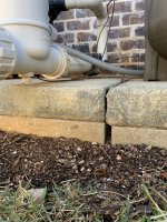
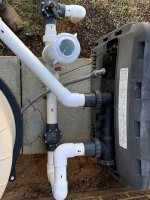
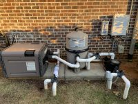
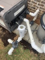
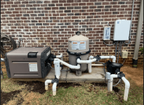
All my equipment is Hayward (see photos):
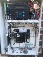
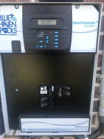
- ProLogic controller with hard wired remote
- Filter
- 2 speed pump
- UV Ozone Generator
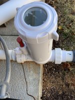
- Chlorinator device
- 400K gas heater
- valve to allow return to both a "bubbler" in a shallow shelf area, and to several returns around the pool
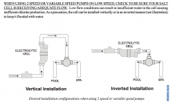
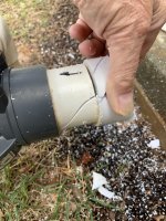
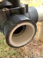
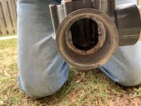
Have read a bit, watched a few videos on installations, etc ... pretty straightforward. Given the layout, it would seem reasonable to plumb the SWG device/water flow sensor horizontally - starting with the heater discharge by repositioning the backflow valve further toward the house, then the SWG device, then the flow sensor, then plumb straight through the existing manual controller valve (removing the chlorination feeder)? If needed, I could extend the outflow from the heater toward the house a couple more inches, but it looks pretty darn close to what is recommended, most of the needed length determined by the flow sensor requirement.
The Hayward "AquaRite" device seems fine, but there are three cells available - 15K gallon, 40K gallon and 40,000 gallon with Extended Life TurboCell. Downside is that the Hayward solution is 2x the cost of some others - my reading indicates there are life span problems with all of them, so is there an advantage to Hayward vs Circupool, vs Jandy vs Pentair vs etc. There must be quality and reliability differences - in addition to the cost differences?
My irregular shaped gunite pool is about 13'x28', 3.5' shallow end and 5.8' deep end. These are conservative estimates/measurements. So, figure 13,000 gallons. Built in 2017. North Florida location.
Some say to size for 2x the volume ... so, 30,000 gallon size? But, manufactures rate by actual volume, so do they account for some engineering conservatism?
All my equipment is Hayward (see photos):
- ProLogic controller with hard wired remote
- Filter
- 2 speed pump
- UV Ozone Generator
- Chlorinator device
- 400K gas heater
- valve to allow return to both a "bubbler" in a shallow shelf area, and to several returns around the pool
Have read a bit, watched a few videos on installations, etc ... pretty straightforward. Given the layout, it would seem reasonable to plumb the SWG device/water flow sensor horizontally - starting with the heater discharge by repositioning the backflow valve further toward the house, then the SWG device, then the flow sensor, then plumb straight through the existing manual controller valve (removing the chlorination feeder)? If needed, I could extend the outflow from the heater toward the house a couple more inches, but it looks pretty darn close to what is recommended, most of the needed length determined by the flow sensor requirement.
The Hayward "AquaRite" device seems fine, but there are three cells available - 15K gallon, 40K gallon and 40,000 gallon with Extended Life TurboCell. Downside is that the Hayward solution is 2x the cost of some others - my reading indicates there are life span problems with all of them, so is there an advantage to Hayward vs Circupool, vs Jandy vs Pentair vs etc. There must be quality and reliability differences - in addition to the cost differences?

 )
)