VGreen 165 Control Panel Issue - possible workarounds using digital inputs

thefisch

Well-known member
Mar 11, 2021
50
Tampa Bay
Pool Size
15000
Surface
Plaster
Chlorine
Salt Water Generator
SWG Type
Solaxx (Saltron) Resilience / Aquacomfort A5
Fan of the forum - finally joined to ask a question before I dive in the deep end.

Installed a VGreen 165 about 4 years ago - the motor has been running fine since, but the start button on the control panel is unresponsive and the motor won’t restart. See background below for more information on why I think the control panel is the issue and not the motor.

As far I can tell, the control panels on the VGreen 165 are not serviceable. From my research, my options seem to be:
  1. Replace the motor
  2. Install the VLink VL100 - not really interested in controlling from my phone or putting $300 into this motor
  3. Install the VGreen 270 User Interface – this is more affordable at $230, but it is not clear how this interface can mount on top of the VGreen 165 as there are no screw holes that appear to line up. With only 6 inches of cable it either goes on top or I'm spending more for an extender.

But after reading threads on here about VGreen 165 automation setups and control panel issues, I thought that maybe I could temporarily run the motor using the digital inputs. It seems from the manual (section 9, on page 23) that the 12v output and com for the RS485 could be jumpered to the digital inputs for step 1 and com. Then I could at least run the pool for a few hours to keep it clean in the meantime. I realize the digital inputs are designed for an external source but it appears that the RS485 could provide the power needed with the correct dip switch setting.

1615523015483.png

Rather than use relays for the different steps, I would just wire step 1 and com and use the timer to turn on and off. This would not be a long-term solution, but might by me some time until I can consider my options.

Anyone have thoughts on my options or jumping the digital inputs?

______________________________________________

Background:

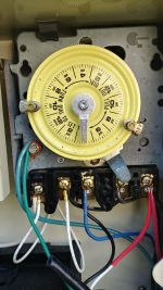
Previously I only used the control panel to tweak the schedule which was seldom. The power to the motor is controlled by an intermatic timer so that the VGreen 165 simply runs it's schedule when the timer kicks the power on.

About 10 months ago, I pressed stop on the control panel (instead of flipping the timer switch) so I could empty the pump basket without restarting the schedule. Afterwards pressing the start button wouldn't register so the motor wouldn't come back on. All the other buttons registered just fine to change the settings for each step, set key lockout, reset to defaults, etc. I was very close to giving up and replacing it when the 500th press of start was the charm and it fired back up. Afterwards, I covered the start/stop buttons with tape so I wouldn't make that mistake again. For the last 10 months the motor ran just fine with the timer controlling the power so I figured the control panel was the issue - not the motor.

All was fine until this week, when someone helping me with the pool pressed the stop button by mistake while fumbling with the steps. Now the motor won't turn on since the start button won't register (despite my best telegraph operator impression).
 
I don’t see any reason why a contact closure from a timer won’t work to trigger one of the Vgreen’s digital inputs. Using that same self powered schematic that you show is exactly how I control the Vgreen pump using a relay in my Jandy automation system. The digital inputs are the highest priority over both the control panel and the Rs-485 interface, so they will control the on/off timing of the motor.
 
  • Like
Reactions: thefisch
I don’t see any reason why a contact closure from a timer won’t work to trigger one of the Vgreen’s digital inputs. Using that same self powered schematic that you show is exactly how I control the Vgreen pump using a relay in my Jandy automation system. The digital inputs are the highest priority over both the control panel and the Rs-485 interface, so they will control the on/off timing of the motor.
Thanks for the response. I was unsure that the control board's own RS485 interface could power it's own digital inputs, but that diagram from the manual made me think it could be possible. Sure it was designed with relays in mind, but if the RS485 provides the 12v directly to the step 1 digital input (and com to com connection too) then it should turn this motor into effectively a single speed motor for the time being. Of course, I need to check that the RS485 will output the 12v - haven't tested that yet.
 
I have my V green setup using a 24v remote power https://smile.amazon.com/gp/product/B07FN83QCR, it is connected to my SWG and when it turns on it powers the 24v and turns on the V green at 1300 rpm, works perfect every time...

I also have the VGreen 270 User Interface – setup right next to the pool and it works great when the pump is off, when the SWG is running it overrides it and does not work...
 
  • Like
Reactions: thefisch
I have the V-Green 1.65 and use only digital inputs to control speed. All my automation does for the pump is turn it on. The inputs are extremely versatile, they can use almost any LV signal from 9-30 v dc or ac. In my system I set Step 1 to run 24 hrs and the lowest speed the salt system will work. Then I wired the LV signal from my heater gas valve into Step 2 at higher speed so I get max heat transfer in the heater coils. Similarly, I split the signal that closes my solar bypass to increase pump speed for it. Your plan to use it for just on and off will be very simple. Not sure what timer you're using but just fine a LV signal that is switched by the time and run it to Step 1 and com. Also, just to be sure a simple fix isn't overlooked cycle the breaker to see if your panel "on-off" switch resets. Seems like this switch may have other functions and a reset routine.

Chris

I did noticed once the override button wasn't working. I could push it but it wouldn't do anything. I did a "reboot" by killing the breaker, pushing a few buttons to drain any stored power and back on that fixed it.
 
Last edited:
  • Like
Reactions: thefisch
Thanks for all the replies. Sorry but was tied up all day on other matters. I did turn off the breaker and waited until all the lights went out on the motor. Pressed some buttons and waited some more just in case. Unfortunately, the start button was still not responsive when power was cycled on again. Tried this again and no difference. Worth a try though.

I have some low voltage bell wire in the garage that I might use this weekend to wire 12v to step 4/override and com to com to see if the RS485 can provide the digital input and get this running again. That way my mechanical timer (at the breaker for the original single speed motor) can initiate power in the morning like before but the digital input would initiate the override function until the mechanical timer shut off.

My understanding with the digital inputs is that the speed of the step is observed but not the time - the step will run until the digital input changes. I was thinking it would be better to use override as I think you can adjust the speed of that setting while it is in use. At least you could when initiating override from the motor - not sure about from the digital input. That would allow me to kick it up to 3100rpm for the pool vac and then drop it down to around 2350 rpm or so for several more hours for the filtration and salt cell to do their thing. If you can't adjust the speed while override is running via digital input then I will just use another step at about 2350 rpm.

I may try some timed relays later to see if I can run a step for a couple of hours at one speed and then run another step until the mechanical timer shuts off. But I've got to see if I can crawl before I walk since this is new to me.
 
  • Sad
Reactions: markayash
I have my V green setup using a 24v remote power Amazon.com: NOYITO AC to DC Precision Buck Power Supply Module AC 110V 100V-264V to 24V 150mA Isolated Step-Down DC Module (24V 150mA): Home Audio & Theater, it is connected to my SWG and when it turns on it powers the 24v and turns on the V green at 1300 rpm, works perfect every time...

I also have the VGreen 270 User Interface – setup right next to the pool and it works great when the pump is off, when the SWG is running it overrides it and does not work...
Thanks for sharing you use the VGreen 270 User interface. Do you have a VGreen 165 also? Where did you install the user interface? I was hoping it could mount on top of the VGreen 165 but not sure that would work.

You are way ahead of me on automation. Near my pool equipment, the original owner had what appears to be low voltage wire installed that goes into the master bedroom, presumably for automation controls. But there is no automation equipment installed at all. I guess I could use that wire to put some kind of timer relay in the house (rather than install outside in the elements). Have to see about getting this motor running first.

I have the V-Green 1.65 and use only digital inputs to control speed. All my automation does for the pump is turn it on. The inputs are extremely versatile, they can use almost any LV signal from 9-30 v dc or ac. In my system I set Step 1 to run 24 hrs and the lowest speed the salt system will work. Then I wired the LV signal from my heater gas valve into Step 2 at higher speed so I get max heat transfer in the heater coils. Similarly, I split the signal that closes my solar bypass to increase pump speed for it. Your plan to use it for just on and off will be very simple. Not sure what timer you're using but just fine a LV signal that is switched by the time and run it to Step 1 and com. Also, just to be sure a simple fix isn't overlooked cycle the breaker to see if your panel "on-off" switch resets. Seems like this switch may have other functions and a reset routine.

Chris
Your thread on your automation was part of my inspiration to try this. So thanks for sharing what you did. In your case, I suppose your start button still works and that mode is the last one stored so that step 1 works for you when step 2 and 3 are not energized. Apparently if you press the stop button, then the steps won't run after the digital input is no longer energized.

My motor and salt system are wired to a basic intermatic mechanical timer. I know I could have run the timer 24/7 and let the VGreen 165 runs its own cycles for the times of each step and then repeat after 24 hours. But with the power blips thanks to Florida storms, using the mechanical timer seemed like a better idea. That way the system is only powered for 10 hours a day at an exact time and the 24 hour cycle doesn't restart at night thanks to a power hiccup. During the 10 hour timer on cycle, I would run the Vgreen 165 through a 2 hour high speed step and then a 6 hour medium speed step. At least I did before this issue.
 

Enjoying this content?

Support TFP with a donation.

Give Support
You’re correct that the Vgreen uses the control panel speed settings but disregards the time settings when using the digital inputs.

The digital inputs all need to be inactive with the motor stopped in order to reprogram any of the control panel speed settings, including override. I just verified this by triggering input 4 (override) and then tried to change the motors running speed via the control panel. The only key on the control panel that does anything is the stop button that puts the motor in a temporary 3 minute stop. But you can’t change the override speed while the digital input is active.
 
Last edited:
  • Like
Reactions: thefisch
"Your thread on your automation was part of my inspiration to try this. So thanks for sharing what you did. In your case, I suppose your start button still works and that mode is the last one stored so that step 1 works for you when step 2 and 3 are not energized. Apparently if you press the stop button, then the steps won't run after the digital input is no longer energized.

My motor and salt system are wired to a basic intermatic mechanical timer. I know I could have run the timer 24/7 and let the VGreen 165 runs its own cycles for the times of each step and then repeat after 24 hours. But with the power blips thanks to Florida storms, using the mechanical timer seemed like a better idea. That way the system is only powered for 10 hours a day at an exact time and the 24 hour cycle doesn't restart at night thanks to a power hiccup. During the 10 hour timer on cycle, I would run the Vgreen 165 through a 2 hour high speed step and then a 6 hour medium speed step. At least I did before this issue."


Thanks for the kind words on my previous post. Yes you're correct and I think you can use the mechanical timer as well. All my automation does is turn the pump on an off just like your timer. I can think of two ways for you to try to get this to work for you:

  1. Use Step 1 one and two. Step 1 runs high speed for two hours and Step 2 runs for 22 more hours at lower speed. When the unit powers down and then restarts your program should start again at Step 1. I seem to recall that in timer mode you have to program 24 hours. I believe the program may be getting messed up since you are not programming 24 hours.
  2. Try to use step 1 instead of step 4. I have programmed mine so that step 1 runs 24 hrs at the lowest speed. It retains this setting through power outages. This will get you running on at least single speed. Is there a way to set your timer with another lug on the wheel such that you can trigger another signal to switch to a higher speed? If so use this to trigger step 2. The way the pump works is it defaults to the internal timer unless there's a digital input. If there's a digital input it over-rides the timer. When it stops the pump reverts to the internal timer. I've never had to use step 4 so that may be why your pump does not retain the programming.

I hope this helps.

Chris

I use to use 2-12 hours programs at different speeds until I started playing around and measuring watts. It was so close I also just let mine run at the same speed ( 2100 rpm ) 24x7.
 
  • Like
Reactions: thefisch
I don’t think @thefisch has the option to use any of the control panel timers to select speed steps because the Start button is broken on his keyboard. So even if you can program the timers there’s no way to execute them.

When the motor starts up it will restart at speed 1, but only if the Start button has been previously pressed. When stopped via the Stop button it won’t do anything upon power up until the Start button is pushed again.

At this point I think the options are:

1. Replace the whole control unit to fix the keyboard.
2. Get the Vlink remote panel and control the motor that way, or
3. Use a digital input and external timer.

Using a digital input and a timer will at least get the pump back in action without having to order other parts.

Mark
 
You all are so awesome helping me with ideas before I can even finish my other errands and find the bell wire in the garage. I truly appreciate it!
You’re correct that the Vgreen uses the control panel speed settings but disregards the time settings when using the digital inputs.

The digital inputs all need to be inactive with the motor stopped in order to reprogram any of the control panel speed settings, including override. I just verified this by triggering input 4 (override) and then tried to change the motors running speed via the control panel. The only key on the control panel that does anything is the stop button that puts the motor in a temporary 3 minute stop. But you can’t change the override speed while the digital input is active.
First, thanks for the tip about the stop button pausing the motor for 3 minutes while running off a digital input. I didn't read that in the manual - the tip could come in handy when a brief pause is needed instead of toggling the flip switch on the mechanical timer.

Too bad you can't make setting adjustments to the speeds for steps or override during that 3 minute pause while digital inputs are still energized. That would have been very convenient. Given my temporary fix (theoretical until I try it later today) will energize the digital input constantly, it sounds like I will have to power motor off, remove wiring to digital input, and then power back on to change any speed settings. Because of this, I think I will wire step 3 which is already programmed for 2350 or 2600 rpm. Using that speed for 10 hours using the mechanical timer should keep the water clean - I don't think 3100 rpm (step 1 for me) for 10 hours is needed.
Is there a way to set your timer with another lug on the wheel such that you can trigger another signal to switch to a higher speed? If so use this to trigger step 2.
My mechanical timer is a simple intermatic with an on/switch. So I don't think it can trigger a second signal - just power on or off. See photos below.
timer.jpg

timer wires.jpg

But maybe I can wire into the transformer for my pool lights. That is 12v 300va transformer and operates off a wall switch in the house that switches on/off the 120v going to the transformer.

lights transformer.jpg

I'd have to verify the voltage of course - not sure if the amps matter or not for a digital input. But it outputs 12v and works for a digital input, then maybe I could connect that to a higher priority digital input such as step 4/override. Then when turning on the pool lights I could trigger override speeds when needed for pool vacuum for a couple of hours or heating the spa (normally I use 3100rpm for these)

I don’t think @thefisch has the option to use any of the control panel timers to select speed steps because the Start button is broken on his keyboard. So even if you can program the timers there’s no way to execute them.

When the motor starts up it will restart at speed 1, but only if the Start button has been previously pressed. When stopped via the Stop button it won’t do anything upon power up until the Start button is pushed again.

At this point I think the options are:

1. Replace the whole control unit to fix the keyboard.
2. Get the Vlink remote panel and control the motor that way, or
3. Use a digital input and external timer.

Using a digital input and a timer will at least get the pump back in action without having to order other parts.

Mark
For the third option, do you mean the Vgreen 270 user interface linked earlier? Or is there a different external timer I could use that could help switch steps?
 

Attachments

  • timer wires.jpg
    timer wires.jpg
    333 KB · Views: 3
Last edited:
SUCCESS! The temporary fix worked great! The motor cranked right up like a hotwired car. Thanks so much for everyone's help.

It was easier than I thought since I could slide up to remove the RS485 interface to insert the wiring and tighten down before putting it back on the interface board. Inserting the bell wires into the digital interface spring connections was easy from above too. See photo of wiring below.

wiring.jpg

As shown in the photo, I connected step 3 at first which was set to 2350rpm. Since it had been a few days since the motor ran, I moved the red wire over (with power off) to override so it could run at 3100 rpm for the next 4-5 hours so the vacumm can get around easier. Tomorrow I will set it up to run at 2350rpm for 10 hours which should be plenty. I figure it is safer to move the 12v wire with the power off even though it would be easier to just flip dip switch 1 to off to cut the 12v power - but that would probably damage the interface board while power is on. Don't need to tempt fate with this motor already having control board issues.

There is room under the interface board if I wanted to slide in a timed relay. This space is about 3 inches wide and 1 inch deep - not sure if that is a usable size space. Will have to see if they make preset 1 or 2 hour timed relays in that size so that I can start out running a higher priority step first.

The digital inputs all need to be inactive with the motor stopped in order to reprogram any of the control panel speed settings, including override. I just verified this by triggering input 4 (override) and then tried to change the motors running speed via the control panel. The only key on the control panel that does anything is the stop button that puts the motor in a temporary 3 minute stop. But you can’t change the override speed while the digital input is active.
@MSchutzer , your description was spot on. No other buttons work except stop while the digital interface is going regardless of the step/override mode. Thanks for your advice. Only minor difference is my motor pauses for 4 minutes when I press stop - timed it just to be certain.

It will fire right back into a priming cycle after 4 minutes regardless, even if you press and hold stop again during the pause. So the pause feature with a digital interface may only be useful for quick valve adjustments or moving the filter mutilport valve for backwashing. Better than nothing for sure!

If anyone has suggestions on timer relays to try, I am all ears. I will look into those more later on.
 
Note that water can sometimes leak into the wiring compartment through the top screw that holds down the wiring compartment cover.

It will run down the post and fill the wiring compartment and short everything out.

Make sure that the screw has an O-ring and maybe put a piece of tape over the screw.
 
  • Like
Reactions: setsailsoon
Note that water can sometimes leak into the wiring compartment through the top screw that holds down the wiring compartment cover.

It will run down the post and fill the wiring compartment and short everything out.

Make sure that the screw has an O-ring and maybe put a piece of tape over the screw.
You can also press a piece of plumbers putty on top of the screw to seal out the water. The putty never hardens and can be removed easily should you need to get back in there.
 
  • Like
Reactions: JamesW
  • Like
Reactions: JamesW

Enjoying this content?

Support TFP with a donation.

Give Support
Thread Status
Hello , This thread has been inactive for over 60 days. New postings here are unlikely to be seen or responded to by other members. For better visibility, consider Starting A New Thread.