COMM conflict between Intelliflo VS Pump and Screenlogic2

jsimonkeller

Member
Oct 3, 2020
17
Nashville TN
Hello. I have been reviewing the forum and cannot find a solution to my problem in other threads.

I have the ET8 system (pool/spa combo) with the Intelliflo VS and Screenlogic2.

I have recently taken my system back to the beginning and erased the EEPROM and started reconnecting everything from scratch.

I have the pool and spa and spillway working just fine, but a problem has arisen.

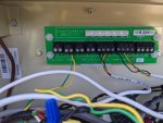
Whenever the Green/Yellow comm cables from the Intelliflo VS are plugged into J20 at the same time as the Green/Yellow comm cables (plus Black/Red) from the Screenlogic antenna, Screenlogic will not respond to commands, but pump shows good connection to the system. When I remove the Green/Yellow wires for the pump, the pump, of course, goes into NO COMM under status, but Screenlogic commands are received from the app without delay. I am using the intellibrite on/off command (Aux 1 and Aux 2) to troubleshoot responsiveness between Screenlogic app and the ET board.

I also have the multiplexer as well (520789), so I hooked the pump up to one of the Green/Yellow connectors and Screenlogic Antenna to one of the Green/Yellow/Black/Red connectors and connected the multiplexer to J20. Again, pump has good comm and Screenlogic nothing. Immediately, as I pull out the pump Green/Yellow connector, Screenlogic immediately responds to commands. I have tried different J ports on the multiplexer and checked the wires and see no crimps or cuts. Again, as long as the pump is disconnected from comm, SL works without a hitch. Best I get is about 30 seconds of responsiveness from SL app and then it stops communicating. I have even swapped out the black connectors to the boards in case it could be that, but no dice.

I am not sure if I need to wire this up differently or if anyone has a suggestion. With all of the troubleshooting I did, I cannot imagine it is a bad board or bad wires.

Thoughts?

JordanPXL_20201127_170846639.jpg
 

Attachments

  • PXL_20201127_170856101.jpg
    PXL_20201127_170856101.jpg
    327.4 KB · Views: 8
Jordan,

On the surface that does not make sense.. :scratch: So, I can see why you are confused..

Just to be clear.. With nothing else connected to J20 but the two wires from the pump and the four wires from ScreenLogic, ScreenLogic does not work, but the pump does. When you run this test you have nothing connected (plugged) into your multiplexer.. Is that correct?

Show more pics or tell use what all is plugged into your multiplexer.. Beside the pump and ScreenLogic, what else do you have that uses the com port? SWCG?? or ???

Let's see if Tom has any ideas... Calling @ogdento

I see a four wire cable coming from your heater (I assume).. Two wires go to the Heater connection in the lower right of your board.. Where do the other two wires go?

Where do the yellow and green wires on the left side of the multiplexer card go??

Thanks,

Jim R.
 
Jim,

Thanks for the quick response. More photos attached.

The ONLY items plugged into the multiplexer and then going into J20 are the Green/Yellow PUMP comm wires and the Blk/Grn/Yellow/Red wires for the SL Antenna. In my photos, the GRN/YELLOW wires on the left are the COMM for the Intelliflo VS. The first Blk/Grn/Yellow/Red wires in the center go to J20 on the ET board and next Blk/Grn/Yellow/Red wires to its right go to the SL Antenna. Again, I have tried a direct connection (without multiplexer) into J20 of both sets of wires at the same time with the same result.

Unfortunately, the pool electrician who hooked everything up did a patchwork job and I am trying to sort it now. Because the equipment is too far from the ET panel to use the included wires, you will see some 4 and 5 wire bundles carrying multiple items, but the wires end up in the rights places.

The GRN/YELLOW wires on the pump comm share a 4 wire run with a WHITE/RED for the water temp sensor. The GRN/BLK on the heater share a 4 wire run with 2 wires (RED/WHT) used for a valve actuator.

I have confirmed all wires go back to the equipment and into the correct components, janky as it looks. At some point, this all worked before I decided to clean things up and reprogram the system from scratch . . .

Hope this extra info and photos helps.
PXL_20201127_182113521.jpgPXL_20201127_182421944.jpg
 
J,

Still a puzzle.. If we assume that all the wiring is good and that the only thing you did was to delete your program, and then reprogram it, I can't think of anything that would cause the problem that you are having. :scratch:

Did it all work with the multiplexer installed, before you reprogrammed it???

Do you have a voltmeter? If so, with the com port to the pump disconnected, measure between the Red and Black pins right at J20's connector and tell me what you have.. I suspect about 18 VDC.. then connect the pump and test the Red and Black pins again, and tell me what you have..

I suspect that either Red or Black wires are being loaded down or that the two data lines (grn and yel) are swapped somewhere.. Maybe not, but logically that is the only thing that makes sense..

I suppose you could have a bent pin, or some weird corrosion right at the connector on the IntelliFlo... ???

You really don't even need the multiplexer, as you only have two RS-485 connections and they can both be connected to J20 at the same time.

Thanks,

Jim R.
 
You say the pump comm wires were patched and extended. Were the Screenlogic data wires also patched and extended?

That extension in the pump comm wires may be causing your problem. Especially with the two comm wires mixed with the current carrying of the temperature sensor.

How was the connection made between the cables?

Is the extension cable twisted pair? Cat5 or what?

The RS-485 protocol uses balanced voltage between the two wires for signaling bits. Wne one wire is high the other is eqully low, or the reverse. Having a current carrying pair next to it can be creating some inductive voltage into the comm line and unbalance the data pair.

I would get good cat5 twisted pair and connect it to the pump comm line and run it to J20. I would not use wire nuts to make the connection and I would use a screw down connection block or solder the wires
 
Thanks again for the responses.

voltmeter reading f 17.2V with pump comm disconnected and same reading with pump comm connected. Same reading on the red/black pins on the multiplexer too. No voltage drops.

I agree that the wiring at the moment is not standard or optimal, but my question is why would the pump work fine with good communication all the time if there was a wiring issue. It is SL that is getting blocked whenever it is plugged in at the same time as the pump. SL antenna is one continuous short wire run and all colors line up. Ultimately, when I have time, I will try to pull new wires that will not have anything sharing one wire jacket. It is NOT twisted pairs, but a 4 wire low voltage cable run.

I swapped the GREEN/YELLOW on the pump COMM and it went into error/no communication, so the wires are not mixed up.

Any other thoughts on why the pump's COMM wires would be interfering with SL?
 
Digital data comm lines work different and are more sensitive then analog power lines that just carry constant voltage. The way RS-485 data lines work is the two lines have equal opposite current to pulse a bit. Your splice has introduced noise or an imbalance where the two data streams of the pump and SL cannot be mixed and understood by the board. The board is able to adjust to hear each one individually but when mixed together on the same bus it does not work.

Your problem is with your spliced data comm cable(s).
 
Jordan,

Did it all work with the multiplexer installed, before you reprogrammed it???

It is an odd one... Does not make sense on the surface..

If this were my system, I would run a temporary 4 wire line from the EasyTouch J20 to the Protocol adapter and see what happens.. This would eliminate the outside antenna as the cause of the problem. I understand that your antenna works when install alone, but not when connected to the pump. Logic says the problem has to be caused by the antenna connection or the pump connection.. I'd want to know which path to follow.

Another wild thought.. the RS-485 works because each item has its own address on the bus.. Maybe something is wrong with whatever determines the address. So one item will work because it is the only item on the bus, but two items don't because the system can't tell the two items apart.. Not saying that is the case, just trying to come up with possible reasons for your problem.

Did the problems start right after you reprogrammed, or did you screw with the com bus before the problem started..

Allen has some great points, but I don't understand how it worked for years before the problem started. :scratch:

Thanks,

Jim R.
 
  • Like
Reactions: MyAZPool
Allen has some great points, but I don't understand how it worked for years before the problem started. :scratch:

I think he jiggled a splice and unbalanced something in the connection.
 
  • Like
Reactions: Jimrahbe

Enjoying this content?

Support TFP with a donation.

Give Support
I appreciate the continued thoughts. I have a ton of Cat5e and Cat 6 cable laying around, so I can test this out tomorrow but running an uninterrupted line (above ground) from the multiplexer to the pump.

Question, for the RS-485 connection, with the 4 twisted pairs on the cable, do I use ONE of the twisted pairs and plug one wire into green and one wire into yellow OR do I use TWO twisted pairs and run one complete twisted pair into GREEN and one complete twisted paid into YELLOW?

At the pump, if I remove the connector at the pump, can I run the unspliced cat5/6 wire right into the pump?

Thanks again fellas!
 
Jim, good idea on running a 4 wire to the protocol adapter. I can try that as well tomorrow.

I think AJ may be right about the noise and moving this around, so I am going to troubleshoot with both of your ideas tomorrow and let you know if anything changes.

Again, this is an odd one because as soon as remove the pump from the multiplexer, the SL comes to life and as soon as it plugs back in, SL goes deal (but the lights still blink on the antenna). Pump seems to be fine the whole time it is plugged in (with or without SL plugged in).

Looks like I have some projects for tomorrow morning :)
 
Just use one pair of twisted wires. The twist in the wires makes a difference.

The pump uses a connector. You cannot connect wires directly to the pump.
 
Last edited:
  • Like
Reactions: MyAZPool
AJ and Jim,

Since I do not have the 50' of pump cable yet, I took the multiplexer out to the pump and connected the short pump comm line to the multiplexer without splices and then connected the multiplexer back to J20 using CAT 5 cable and connected the SL antenna to J20 unspliced and it seems to be working without any conflict.

Thanks for the help on this. Once the longer cable arrives, I can use that one to get everything back to the ET cabinet.
PXL_20201128_181121249.jpgPXL_20201128_181219230.jpg
 
Nice one!! @ajw22 and @jsimonkeller
Just goes to illustrate how a simple bad splice can really throw a monkey in the works.
I've been "lurking" on this thread to see if I might learn something and I'm really glad to see that it wasn't anything more complicated (or expensive). ;)
59.jpg
 
Are there any electrical components on the backside of the Pentair multiplex board? It looks like the board is a simple connection block for the Pentair RS-485 comm protocol.
 

Enjoying this content?

Support TFP with a donation.

Give Support
Thread Status
Hello , This thread has been inactive for over 60 days. New postings here are unlikely to be seen or responded to by other members. For better visibility, consider Starting A New Thread.