| (44 intermediate revisions by 3 users not shown) | |||
| Line 1: | Line 1: | ||
| + | [[Category:Swimming Pool Equipment]] | ||
| + | |||
=Hayward ProLogic= | =Hayward ProLogic= | ||
| − | + | ||
[[File:Hayward GLX-PCB-PRO Board.jpg|thumb]] | [[File:Hayward GLX-PCB-PRO Board.jpg|thumb]] | ||
| − | ProLogic uses the GLX-PCB-PRO board. | + | Goldline introduced AquaLogic in 2003. Hayward acquired Goldline in August of 2004. Hayward discontinued AquaLogic in 2008 and replaced it with Prologic. [https://hayward-pool-assets.com/assets/documents/pools/pdf/literature/automation-LITAUTOB15.pdf Hayward Automation Guide] describes the different versions of the Prologic system and its capabilities. |
| + | |||
| + | The Prologic system comes in three models: | ||
| + | *P-4 - pool only 4 relays | ||
| + | *PS-4 - pool/spa 4 relays | ||
| + | *P-8 - pool/spa 8 relays | ||
| + | |||
| + | There is also an PS-16 Prologic expansion unit that adds another 8 relays to a PS-8 system. | ||
| + | |||
| + | With the Prologic system you separately select the SWG cell - T-3, T-9, T-15 - for the system. | ||
| + | |||
| + | The AquaPlus system is a Prologic PS-4 or PS-8 bundled with a T-15 cell. | ||
| + | |||
| + | ProLogic uses the GLX-PCB-PRO board. The latest firmware is 4.47. It takes a special programming tool to update the ProLogic ROM.<ref> https://www.troublefreepool.com/threads/prologic-firmware-version-4-47.244701/ </ref> | ||
| + | |||
| + | The Chemistry Sensing Module is a separate system for PH and ORP monitoring and some people fell is a waste of money.<ref> https://www.troublefreepool.com/threads/hayward-aqua-plus-check-system-light-on.191535/post-1688455</ref> | ||
| + | |||
| + | [https://hayward.com/media/wysiwyg/pdf/automation/PL447c-ProLogic_TSG.pdf ProLogic Troubleshooting Guide] and [http://splashottawa.com/wp-content/uploads/2016/05/Pro-Logic-Diagnostics.pdf ProLogic Version 4.45 Diagnostics Manual] are good places to start with problems. | ||
| + | |||
| + | [[File:Hayward Prologic circuit board layout.png|frameless]] | ||
| + | [[File:Hayward ProLogic Board Illustrated Components.png|thumb]] | ||
| + | |||
| + | [https://www.totallyhayward.com/pdfs/authorized_online_sellers_table.pdf Hayward Authorized Online Sellers] shows which online sellers are authorized Hayward dealers. | ||
| + | ==SWG Cell Basic Diagnostics== | ||
| + | |||
| + | *Report all readings when you.. | ||
| + | **Go to the diagnostic screen, note the readings and then press the + button to reverse the polarity. | ||
| + | **When the new numbers appear, see what they are. | ||
| + | **Then, press + again and note the new readings. | ||
| + | *What are the first seven characters of the cell and box serial numbers? | ||
| + | *What is the actual salinity and how are you measuring it? | ||
| + | |||
| + | ==Repairing the Main Board== | ||
| + | [https://www.haywardboardrepair.com/ B&L Enterprises] will repair Hayward boards if you are not comfortable doing board level repairs. | ||
| + | |||
| + | https://www.digikey.com/en/products/detail/cantherm/MF72-050D9/1190943 | ||
| + | |||
| + | ==Configuration Menu-Locked== | ||
| + | Press the ‘Menu’ until, ‘Configuration Menu-Locked’ appears. To unlock, press and hold the (<) & (>) keys until the text on the display changes from ‘Locked’ to ‘Unlocked’. | ||
| + | |||
| + | ==Freeze Protection== | ||
| + | The freeze protection temperature is adjustable from 33º F to 42º F (38ºF is the default). Go to configuration and set freeze temperature as you like. Unlock configuration by pressing < > at the same time for 10 seconds.<ref> https://www.troublefreepool.com/threads/prologic-freeze-protection.108200/post-949302</ref> | ||
| + | |||
| + | ProLogic freeze protection uses air temperature, not water temperature. If you are having problems with freeze protection cycling verify that the air and water temperature readings are accurate and that the sensors are not switched (air sensor connected to the water sensor terminal). | ||
| + | |||
| + | ==Spa Spillover== | ||
| + | You can enable the Spa Spillover in the Configuration Menu. | ||
| + | |||
| + | To schedule the spa spillover to run automatically you use a GROUP function assigned to an AUX button. The GROUP function uses an AUX button and an AUX relay. | ||
| + | |||
| + | You either need to pick an AUX relay that has no equipment connected to it or if you have no empty AUX relays then you need to combine some equipment to create an empty a relay for the spillover function. | ||
| + | |||
| + | There is no way to decouple the AUX button for the spillover from the relay with the equipment it powers. | ||
| + | |||
| + | You can only assign one time period to each AUX button.<ref> https://www.troublefreepool.com/threads/spillover-question.195423/post-1722887</ref> | ||
| + | |||
| + | However if you have two extra AUX buttons and relays available, you can assign different time periods to each while having the same functions. | ||
| + | |||
| + | The only downside to a GROUP function is that it uses one of the AUX relays. | ||
| + | |||
| + | ==Flow Monitoring== | ||
| + | |||
| + | If a flow switch is installed Flow Monitoring can be enabled in the Configuration. If Flow Monitoring is enabled then if there’s no flow for 15 minutes, the system will shut off the pump to protect it and the check status light will go on. | ||
| + | |||
| + | [[File:Hayward Prologic Flow Monitoring Enabled.png|thumb]] | ||
| + | |||
| + | This is the same flow switch that is used to control the Aquarite SWG cell. Flow switch monitoring and control of the SWG cell cannot be disabled. | ||
| + | |||
| + | This [https://www.youtube.com/watch?v=QdCzckWGhD0&t=40s Hayward YouTube video] shows how to set the Flow Monitor. | ||
| + | |||
| + | ==Relays== | ||
| + | |||
| + | High voltage relays are GLX-RELAY and uses 24V DC. | ||
| + | |||
| + | [https://www.amazon.com/Hayward-AQL-RELAY-AC-KT-240-volt-Replacement-Automation/dp/B002NHZKSA Hayward AQL-RELAY-AC-KT 3 HP 240-volt High AC voltage Relay Replacement Kit for Hayward Pool Automation and Control Systems] uses 24V AC and is designed to be used in a valve actuator socket. This can be used if you have used all the AUX relays and have actuator sockets free. | ||
| + | |||
| + | ==U4/U5 Relay Driver Failure== | ||
| + | |||
| + | The U4 and U5 chips are Micrel MIC5841/5842 relay drivers<ref>https://www.mouser.com/datasheet/2/268/mic5841-779182.pdf</ref> that control the K1, K2, K3, actuator and power relays.<ref>https://www.troublefreepool.com/threads/board-repair.286442/post-2510541</ref> | ||
| + | |||
| + | A relay failure can blow out the driver chip. If you replace them, you might want to test continuity on the relays to make sure they are not shorted. | ||
| + | |||
| + | [[File:Hayward Aqualogic U4 Driver Failure.jpg|thumb]] | ||
| + | |||
| + | When a member replaced the U4/U5 chips he added sockets so they could be easily replaced again.<ref>https://www.troublefreepool.com/threads/board-repair.286442/post-2510541</ref> | ||
| + | |||
| + | Parts used were: | ||
| + | *[https://www.digikey.com/en/products/detail/microchip-technology/MIC5841YN/771776 MIC5841YN IC PWR DRIVER BIPOLAR 1:8 18DIP] | ||
| + | *[https://www.digikey.com/en/products/detail/on-shore-technology-inc/ED18DT/4147597 ED18DTCONN IC DIP SOCKET 18POS TIN] | ||
| + | |||
| + | [[File:Hayward Prologic Socketed U4 U5 Drivers.png|thumb]] | ||
==CMS comm error== | ==CMS comm error== | ||
| − | CSM | + | The CSM (Chemistry Sensing Module) comm error appears when Sense & Dispense is enabled, but the Chemistry Sensing Module is not found.<ref> https://www.troublefreepool.com/threads/hayward-goldline-aqua-plus.194999/post-1718637</ref> |
If yes, verify that it's plugged in. | If yes, verify that it's plugged in. | ||
| − | If no, disable Sensing System in the Configuration Menu. | + | If no, disable Sensing System in the Configuration Menu.<ref> https://www.troublefreepool.com/threads/hayward-aqua-plus-check-system-light-on.191535/</ref> |
| + | |||
| + | ==Buttons Become Unresponsive== | ||
| + | |||
| + | Usually when the buttons become unresponsive the fix is to replace the display board. Before you buy a new board you can try this repair sort of under Murphy's Laws....go ahead and try it, if you break it you had to replace it anyway:<ref>https://www.troublefreepool.com/threads/hayward-goldline-aqua-plus-menu-button-no-tworking-on-panel.138410/post-1228214</ref> | ||
| + | |||
| + | *Turn off the power to the panel | ||
| + | *Remove SWG cord | ||
| + | *Remove the 3 screws holding on the steel plate | ||
| + | *Remove the display board (it sits on 4 nylon posts) and unplug (be sure to note orientation of wires, I don't think it was keyed) | ||
| + | *Remove the screws holding in the pc board to the display unit and remove it. T6 screws hold the PCB to the case. | ||
| + | *"button" pad will then be exposed, carefully peel back and look for discoloration/corrosion on the contacts | ||
| + | *Clean carefully the pc board "contacts" with some q-tips dipped in alcohol | ||
| + | *For heavier oxidation, try a pencil eraser but do not rub too hard - do not scrape with a sharp metal object or sandpaper | ||
| + | *Clean rubber "button" pad with alcohol and let dry before reassembly | ||
| + | *Power it back up and see how you made out | ||
| + | |||
| + | Here is a [https://www.youtube.com/watch?v=gVr8eLW0-_o youtube video] on cleaning the contacts for another piece of equipment to give you an idea how to clean the buttons, the principals are the same. | ||
| + | |||
| + | [https://www.troublefreepool.com/threads/how-to-reset-hayward-swcg.247691/ Here is a successful key cleaning thread]. | ||
| + | |||
| + | ==ProLogic Cavitation Alarm== | ||
| + | |||
| + | When connected to a variable speed pump(VSP), a ProLogic will display Error Code: 80 if the VSP detects pump cavitation.<ref>https://www.totallyhayward.com/techservices/attachments/Technical%20Updates%20for%20Pool%20Professionals%20Aug%202020.pdf</ref> | ||
| + | |||
| + | A cavitation alarm signals that the pump is experiencing uncommon vibrations. Sometimes referred to as a “noisy pump”. This problem can be resolved by checking for: | ||
| + | *Air leak in suction piping, cavitations caused by restricted or undersized suction line or leak at any joint, low water level in pool, and unrestricted discharge return lines. Correct the suction condition or throttle return lines, if practical. Holding your hand over the return fitting will sometimes prove this, or by putting in a smaller eyeball fitting. | ||
| + | *Vibration due to improper mounting, etc. Mount the pump on a level surface and secure the pump to the equipment pad. | ||
| + | *Foreign matter in the pump housing. Loose stones/debris hitting the impeller could be the cause. Clean the pump housing. | ||
| + | *Motor bearings noisy from normal wear, rust, overheating, or concentration of chemicals causing seal damage, which will allow chlorinated water to seep into bearings wiping out the grease causing bearing to whine. All seal leaks should be replaced at once. | ||
| + | |||
| + | ==Heater Status - Clean== | ||
| + | |||
| + | The ProLogic display SETTINGS shows the pool in POOL CLEAN MODE OFF and SPA CLEAN MODE OFF. When you go into SETTINGS on the ProLogic panel you no longer see Pool Heater1 or Spa Heater1 so you cant adjust temps. | ||
| + | |||
| + | [[File:Hayward Prologic Heater Clean Mode.jpg|400px|frameless]] | ||
| + | |||
| + | The "Clean" heater LED is saying that your Heater is in the "Off Mode"<ref>https://www.troublefreepool.com/threads/hayward-h400fdn-heater-clean-mode-help-requested.249597/post-2187048</ref> | ||
| + | |||
| + | If your Settings Menu isn't featuring Heater 1 Spa or Pool Heat Set Points then you may have it Configured to "Disabled" | ||
| + | |||
| + | Follow the instructions below: | ||
| + | |||
| + | *Press Menu to Configuration | ||
| + | *Unlock with Both Left and Right Arrows (same time until unlocks) | ||
| + | *Right Arrow to Heater 1 Config then Press + | ||
| + | *If Disabled, please Enable by pressing + | ||
| + | *Press Menu back to Settings Menu | ||
| + | *Right Arrow, both Spa and Pool should now be present. | ||
| + | |||
| + | ==AQL2-POD2 Battery Replacement== | ||
| + | |||
| + | The Hayward AQL2-POD2 - AquaPod 2.0 Touchscreen Wireless Remote can be used in the ProLogic, AquaPlus, OnCommand, E-Command 4 automation systems. | ||
| + | |||
| + | It's simply a matter of finding a battery with the third thermistor wire and swapping connectors:<ref>https://www.troublefreepool.com/threads/aql2-pod2-successful-battery-replacement.251217/post-2199094</ref> | ||
| + | |||
| + | #Find a battery on Amazon or eBay that meets the requirements: 3.7V and 1130mAh. The 3.7V is a must, and the mAh can be more, but not much more without making the physical size too big. Here's the one I used from [https://www.amazon.com/gp/product/B00EDQ6LZ0/ref=ppx_yo_dt_b_asin_title_o03_s00?ie=UTF8&psc=1 Amazon], and here's a link from [https://www.ebay.com/itm/174912548708?mkcid=16&mkevt=1&mkrid=711-127632-2357-0&ssspo=tHlHTpHLQsW&sssrc=2047675&ssuid=&widget_ver=artemis&media=COPY eBay] for a variety of sizes and connectors. I never did sort out if any of those on eBay was already the right connector, but I was not optimistic. | ||
| + | #Get yourself a T-8 torx screwdriver to remove the back panel of the remote. This is the square POD 2 remote, and not the original handheld version. 6 screws and you're good to go. | ||
| + | #Remove back panel, set aside. | ||
| + | #Disconnect battery. And a warning: you need a soldering iron and nimble fingers to make the connections work since the wires are a bit small. But definitely doable. | ||
| + | #Cut the wires on the original battery close to the battery so as to give yourself some extra wire to work with. This is an act of faith - I cut half way in case I had to go back, but I would go all the way to the battery if I did so again. | ||
| + | #Cut the wires on the replacement battery close to the connector. | ||
| + | #Solder red-red, black-black, yellow-yellow. Insulate each wire with electrical tape. | ||
| + | #Reconnect battery, screw on cover. | ||
| + | #Done. Place in cradle to charge. | ||
| + | . | ||
Latest revision as of 19:36, 16 April 2024
Hayward ProLogic
Goldline introduced AquaLogic in 2003. Hayward acquired Goldline in August of 2004. Hayward discontinued AquaLogic in 2008 and replaced it with Prologic. Hayward Automation Guide describes the different versions of the Prologic system and its capabilities.
The Prologic system comes in three models:
- P-4 - pool only 4 relays
- PS-4 - pool/spa 4 relays
- P-8 - pool/spa 8 relays
There is also an PS-16 Prologic expansion unit that adds another 8 relays to a PS-8 system.
With the Prologic system you separately select the SWG cell - T-3, T-9, T-15 - for the system.
The AquaPlus system is a Prologic PS-4 or PS-8 bundled with a T-15 cell.
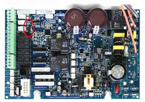
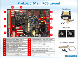
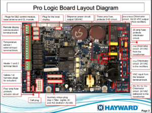
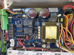
ProLogic uses the GLX-PCB-PRO board. The latest firmware is 4.47. It takes a special programming tool to update the ProLogic ROM.[1]
The Chemistry Sensing Module is a separate system for PH and ORP monitoring and some people fell is a waste of money.[2]
ProLogic Troubleshooting Guide and ProLogic Version 4.45 Diagnostics Manual are good places to start with problems.
Hayward Authorized Online Sellers shows which online sellers are authorized Hayward dealers.
SWG Cell Basic Diagnostics
- Report all readings when you..
- Go to the diagnostic screen, note the readings and then press the + button to reverse the polarity.
- When the new numbers appear, see what they are.
- Then, press + again and note the new readings.
- What are the first seven characters of the cell and box serial numbers?
- What is the actual salinity and how are you measuring it?
Repairing the Main Board
B&L Enterprises will repair Hayward boards if you are not comfortable doing board level repairs.
https://www.digikey.com/en/products/detail/cantherm/MF72-050D9/1190943
Configuration Menu-Locked
Press the ‘Menu’ until, ‘Configuration Menu-Locked’ appears. To unlock, press and hold the (<) & (>) keys until the text on the display changes from ‘Locked’ to ‘Unlocked’.
Freeze Protection
The freeze protection temperature is adjustable from 33º F to 42º F (38ºF is the default). Go to configuration and set freeze temperature as you like. Unlock configuration by pressing < > at the same time for 10 seconds.[3]
ProLogic freeze protection uses air temperature, not water temperature. If you are having problems with freeze protection cycling verify that the air and water temperature readings are accurate and that the sensors are not switched (air sensor connected to the water sensor terminal).
Spa Spillover
You can enable the Spa Spillover in the Configuration Menu.
To schedule the spa spillover to run automatically you use a GROUP function assigned to an AUX button. The GROUP function uses an AUX button and an AUX relay.
You either need to pick an AUX relay that has no equipment connected to it or if you have no empty AUX relays then you need to combine some equipment to create an empty a relay for the spillover function.
There is no way to decouple the AUX button for the spillover from the relay with the equipment it powers.
You can only assign one time period to each AUX button.[4]
However if you have two extra AUX buttons and relays available, you can assign different time periods to each while having the same functions.
The only downside to a GROUP function is that it uses one of the AUX relays.
Flow Monitoring
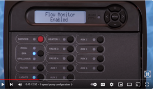
If a flow switch is installed Flow Monitoring can be enabled in the Configuration. If Flow Monitoring is enabled then if there’s no flow for 15 minutes, the system will shut off the pump to protect it and the check status light will go on.
This is the same flow switch that is used to control the Aquarite SWG cell. Flow switch monitoring and control of the SWG cell cannot be disabled.
This Hayward YouTube video shows how to set the Flow Monitor.
Relays
High voltage relays are GLX-RELAY and uses 24V DC.
Hayward AQL-RELAY-AC-KT 3 HP 240-volt High AC voltage Relay Replacement Kit for Hayward Pool Automation and Control Systems uses 24V AC and is designed to be used in a valve actuator socket. This can be used if you have used all the AUX relays and have actuator sockets free.
U4/U5 Relay Driver Failure
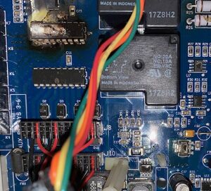
The U4 and U5 chips are Micrel MIC5841/5842 relay drivers[5] that control the K1, K2, K3, actuator and power relays.[6]
A relay failure can blow out the driver chip. If you replace them, you might want to test continuity on the relays to make sure they are not shorted.
When a member replaced the U4/U5 chips he added sockets so they could be easily replaced again.[7]
Parts used were:
CMS comm error
The CSM (Chemistry Sensing Module) comm error appears when Sense & Dispense is enabled, but the Chemistry Sensing Module is not found.[8]
If yes, verify that it's plugged in.
If no, disable Sensing System in the Configuration Menu.[9]
Buttons Become Unresponsive
Usually when the buttons become unresponsive the fix is to replace the display board. Before you buy a new board you can try this repair sort of under Murphy's Laws....go ahead and try it, if you break it you had to replace it anyway:[10]
- Turn off the power to the panel
- Remove SWG cord
- Remove the 3 screws holding on the steel plate
- Remove the display board (it sits on 4 nylon posts) and unplug (be sure to note orientation of wires, I don't think it was keyed)
- Remove the screws holding in the pc board to the display unit and remove it. T6 screws hold the PCB to the case.
- "button" pad will then be exposed, carefully peel back and look for discoloration/corrosion on the contacts
- Clean carefully the pc board "contacts" with some q-tips dipped in alcohol
- For heavier oxidation, try a pencil eraser but do not rub too hard - do not scrape with a sharp metal object or sandpaper
- Clean rubber "button" pad with alcohol and let dry before reassembly
- Power it back up and see how you made out
Here is a youtube video on cleaning the contacts for another piece of equipment to give you an idea how to clean the buttons, the principals are the same.
Here is a successful key cleaning thread.
ProLogic Cavitation Alarm
When connected to a variable speed pump(VSP), a ProLogic will display Error Code: 80 if the VSP detects pump cavitation.[11]
A cavitation alarm signals that the pump is experiencing uncommon vibrations. Sometimes referred to as a “noisy pump”. This problem can be resolved by checking for:
- Air leak in suction piping, cavitations caused by restricted or undersized suction line or leak at any joint, low water level in pool, and unrestricted discharge return lines. Correct the suction condition or throttle return lines, if practical. Holding your hand over the return fitting will sometimes prove this, or by putting in a smaller eyeball fitting.
- Vibration due to improper mounting, etc. Mount the pump on a level surface and secure the pump to the equipment pad.
- Foreign matter in the pump housing. Loose stones/debris hitting the impeller could be the cause. Clean the pump housing.
- Motor bearings noisy from normal wear, rust, overheating, or concentration of chemicals causing seal damage, which will allow chlorinated water to seep into bearings wiping out the grease causing bearing to whine. All seal leaks should be replaced at once.
Heater Status - Clean
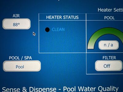
The ProLogic display SETTINGS shows the pool in POOL CLEAN MODE OFF and SPA CLEAN MODE OFF. When you go into SETTINGS on the ProLogic panel you no longer see Pool Heater1 or Spa Heater1 so you cant adjust temps.
The "Clean" heater LED is saying that your Heater is in the "Off Mode"[12]
If your Settings Menu isn't featuring Heater 1 Spa or Pool Heat Set Points then you may have it Configured to "Disabled"
Follow the instructions below:
- Press Menu to Configuration
- Unlock with Both Left and Right Arrows (same time until unlocks)
- Right Arrow to Heater 1 Config then Press +
- If Disabled, please Enable by pressing +
- Press Menu back to Settings Menu
- Right Arrow, both Spa and Pool should now be present.
AQL2-POD2 Battery Replacement
The Hayward AQL2-POD2 - AquaPod 2.0 Touchscreen Wireless Remote can be used in the ProLogic, AquaPlus, OnCommand, E-Command 4 automation systems.
It's simply a matter of finding a battery with the third thermistor wire and swapping connectors:[13]
- Find a battery on Amazon or eBay that meets the requirements: 3.7V and 1130mAh. The 3.7V is a must, and the mAh can be more, but not much more without making the physical size too big. Here's the one I used from Amazon, and here's a link from eBay for a variety of sizes and connectors. I never did sort out if any of those on eBay was already the right connector, but I was not optimistic.
- Get yourself a T-8 torx screwdriver to remove the back panel of the remote. This is the square POD 2 remote, and not the original handheld version. 6 screws and you're good to go.
- Remove back panel, set aside.
- Disconnect battery. And a warning: you need a soldering iron and nimble fingers to make the connections work since the wires are a bit small. But definitely doable.
- Cut the wires on the original battery close to the battery so as to give yourself some extra wire to work with. This is an act of faith - I cut half way in case I had to go back, but I would go all the way to the battery if I did so again.
- Cut the wires on the replacement battery close to the connector.
- Solder red-red, black-black, yellow-yellow. Insulate each wire with electrical tape.
- Reconnect battery, screw on cover.
- Done. Place in cradle to charge.
.
- ↑ https://www.troublefreepool.com/threads/prologic-firmware-version-4-47.244701/
- ↑ https://www.troublefreepool.com/threads/hayward-aqua-plus-check-system-light-on.191535/post-1688455
- ↑ https://www.troublefreepool.com/threads/prologic-freeze-protection.108200/post-949302
- ↑ https://www.troublefreepool.com/threads/spillover-question.195423/post-1722887
- ↑ https://www.mouser.com/datasheet/2/268/mic5841-779182.pdf
- ↑ https://www.troublefreepool.com/threads/board-repair.286442/post-2510541
- ↑ https://www.troublefreepool.com/threads/board-repair.286442/post-2510541
- ↑ https://www.troublefreepool.com/threads/hayward-goldline-aqua-plus.194999/post-1718637
- ↑ https://www.troublefreepool.com/threads/hayward-aqua-plus-check-system-light-on.191535/
- ↑ https://www.troublefreepool.com/threads/hayward-goldline-aqua-plus-menu-button-no-tworking-on-panel.138410/post-1228214
- ↑ https://www.totallyhayward.com/techservices/attachments/Technical%20Updates%20for%20Pool%20Professionals%20Aug%202020.pdf
- ↑ https://www.troublefreepool.com/threads/hayward-h400fdn-heater-clean-mode-help-requested.249597/post-2187048
- ↑ https://www.troublefreepool.com/threads/aql2-pod2-successful-battery-replacement.251217/post-2199094


