
- Aug 22, 2017
- 2,996
- Pool Size
- 15000
- Surface
- Plaster
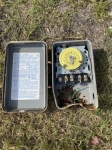
- Chlorine
- Salt Water Generator
- SWG Type
- Hayward Aqua Rite (T-15)
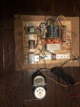
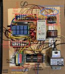
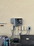
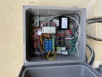
Nothing like an impending hurricane to give you time for fun stuff. All the shutters were up and in-laws came to the house so managed to carve out a little time to work on the controller. Cut a piece of plywood the size of the box I plan on mounting it in so I have a template to check all the sizes. Have the pump relay, heater, SWG, Stenner relays all wired. Pump will be 240v and everything else will be set for 120v. Have a 5v power supply, and a 24VAC transformer. 16 relays, 8 for the actuators, and 4 for power, and 2 more for the heater control.
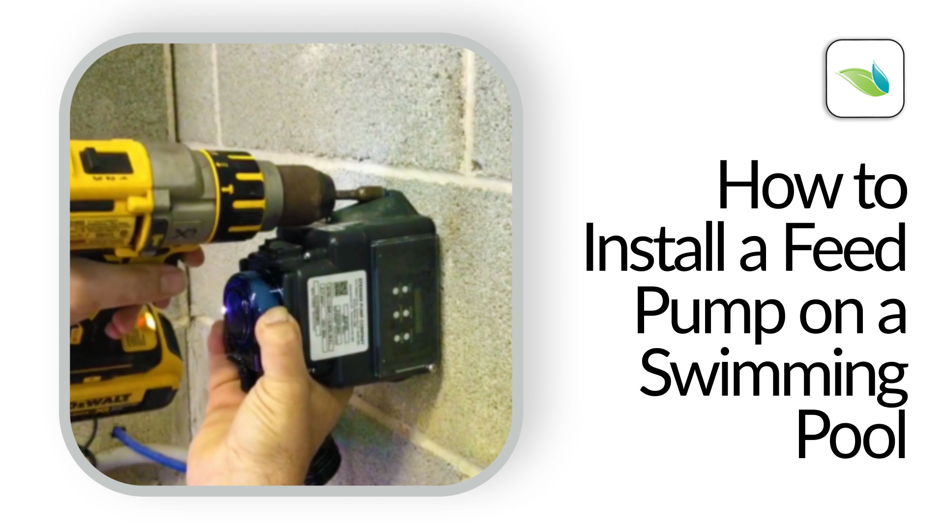
Going to have to change the programming a little since I am thinking I am going to use the Pentair Intellivalves. Which I have successfully tested with relay control. They need continual power which is different than the standard relays.
Going to have to change the programming a little since I am thinking I am going to use the Pentair Intellivalves. Which I have successfully tested with relay control. They need continual power which is different than the standard relays.


.png)