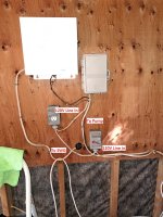
Hello,
The previous owners of my home had the pool pump on a timer switch but the SWG was just plugged into a receptacle. I found that the flow switch is not always reliable, allowing the SWG to run even when the pump is off. I have heard that the pump and SWG should be on the same timer switch to avoid this. My timer is a GE 15252 (https://usermanual.wiki/Document/GE152511525215253Instructions.3344179321/view), with 8 terminals. Terminals are currently connected as follows, from left to right:
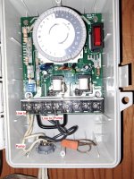
Timer
1 The white (hot) wires from the line in and the pump are connected to terminal one
2 There is a black (neutral) wire from the line in and a jumper wire on terminal two
NC1 - not used
NO1 - black wire for the pump
COM1 - black wire for jumper from timer terminal 2
NC2, NO2, COM2 - not used
The Line and Pump grounds are connected together with a twist-on connector
I verified with a multimeter that between terminal 1 and ground is 120V and between terminal 2 and ground is 0V.
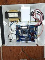
If I want to connect my SWG to the timer switch, what would be the best way? I was thinking:
-Connect the two white wires (for the pump and the SWG) and a third wire together with a twist-on connector, then run the third wire to terminal 1
-Connect the black wire from the SWG to the NO1 terminal
-Connect all grounds together with a twist-on
Would this be a sound way of getting the SWG and pump to turn on at the same time?
I've attached some pictures to help clarify things.
The previous owners of my home had the pool pump on a timer switch but the SWG was just plugged into a receptacle. I found that the flow switch is not always reliable, allowing the SWG to run even when the pump is off. I have heard that the pump and SWG should be on the same timer switch to avoid this. My timer is a GE 15252 (https://usermanual.wiki/Document/GE152511525215253Instructions.3344179321/view), with 8 terminals. Terminals are currently connected as follows, from left to right:
Timer
1 The white (hot) wires from the line in and the pump are connected to terminal one
2 There is a black (neutral) wire from the line in and a jumper wire on terminal two
NC1 - not used
NO1 - black wire for the pump
COM1 - black wire for jumper from timer terminal 2
NC2, NO2, COM2 - not used
The Line and Pump grounds are connected together with a twist-on connector
I verified with a multimeter that between terminal 1 and ground is 120V and between terminal 2 and ground is 0V.
If I want to connect my SWG to the timer switch, what would be the best way? I was thinking:
-Connect the two white wires (for the pump and the SWG) and a third wire together with a twist-on connector, then run the third wire to terminal 1
-Connect the black wire from the SWG to the NO1 terminal
-Connect all grounds together with a twist-on
Would this be a sound way of getting the SWG and pump to turn on at the same time?
I've attached some pictures to help clarify things.