Wiring a timer

primuspaul

Well-known member
Sep 3, 2018
129
NYC area
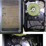
I want to install a timer for my pool. There is already a timer installed, but it appears as though it is broken. The clock does not turn, so the only way to use it is to flip the manual switch, which toggles the pump on and off. I bought the same model # timer, but it appears as though it is different. Here is what the current installation looks like. It is wired well enough so that the manual switch turns the pump on/off. Other than that, I don't know:
old.jpg
(left to right labeled Line 1, Line 2, Load 1, Load 2)

New item I bought:
new.jpg
(not including the left-most screw, the four main screws are labeled 1, 2, 3, and 4 left to right)

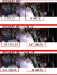
Tests with a multimeter of the currently installed (broken) unit:
oldVOLTAGE.jpg

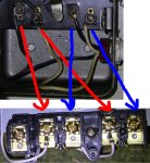
If I understand correctly, I need to connect the wires to the new unit as such:
wiringdiagram.jpg

Does that seem correct?

Oh, and on the pump end, the pump is jumpered for 230v, and that's the voltage coming out of the two wires (there's also a third ground wire going to the green screw).
 
Last edited:
Your old timer is ancient.

You have the wiring correct. Rather then LIne1, LINE2, LOAD1, LOAD2 the connections are now LINE1, LOAD1, LINE2, LOAD2.
 
Your old timer is ancient.

You have the wiring correct. Rather then LIne1, LINE2, LOAD1, LOAD2 the connections are now LINE1, LOAD1, LINE2, LOAD2.
Thanks. I was about to get started, assuming the screws were positioned the same, but then I saw they spaced them out, presumably to help reduce the chance of a short circuit. I will follow the arrows I drew based on your advice and already labeled the wires based on their current connection so I don't forget once I disconnect them. I assume the thing is safe to touch with that particular breaker switch off (power to the rest of house is still on)?
 
I assume the thing is safe to touch with that particular breaker switch off (power to the rest of house is still on)?

Yes but always double check power is off the wires with a circuit tester or voltmeter.
 
Well, it seems to be working. Was working earlier on ON mode. I just turned it to OFF mode (timer mode) to see if it will work. I do see one of the gears in the back slowly moving so I assume it's fine. Only time will tell.

Despite looking different, the board fit into the old box quite well after I fiddled with it a bit. Only real worry was if one of the wires would reach due to the different configuration (and distance from switchboard) of some of the screws, but it looks like the wire did have some extra length to it inside the switchboard and came right out. Might have been even easier if those wires had ring terminals on them, but the hooked wire ends seem to work just fine.

By the time I was done, the wire labels had come off. Not a big deal now, but are there more durable ones, perhaps made of nylon that I could buy?
 
Thread Status
Hello , This thread has been inactive for over 60 days. New postings here are unlikely to be seen or responded to by other members. For better visibility, consider Starting A New Thread.