I know it's been posted but I'm not sure if my wiring is different so just decided to get some advice here. Pool builder says he has never installed one and prefers I call an electrician. TIA

Wifi timer wiring
- Thread starter artu4bbk
- Start date
You are using an out of date browser. It may not display this or other websites correctly.
You should upgrade or use an alternative browser.
You should upgrade or use an alternative browser.
Art,
Normally when you look at a timer you expect to see certain things and not see other things..
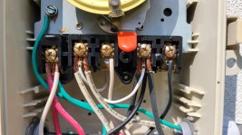
It appears that you have ground (green) and neutral (white) wires connected together, which is not normal.
It appears you have a red wire connected to this same ground and neutral wiring, again odd as most red wires are hot.
I assume that the pins 2 and 4 are the outputs, but you did not tell us what specific timer you have so that may not be true.
It appears that the timer is switching both the hot leg as well as the neutral wire which is almost never done.
So, even though I almost always try to help someone electrocute themselves, we need more info and a pic showing the wiring from a step or two back so we can see all the inputs and outputs. Tell us which timer you have. Tell us what the timer controls.. Tell use what conduits goes where.
Thanks,
Jim R.
Normally when you look at a timer you expect to see certain things and not see other things..
It appears that you have ground (green) and neutral (white) wires connected together, which is not normal.
It appears you have a red wire connected to this same ground and neutral wiring, again odd as most red wires are hot.
I assume that the pins 2 and 4 are the outputs, but you did not tell us what specific timer you have so that may not be true.
It appears that the timer is switching both the hot leg as well as the neutral wire which is almost never done.
So, even though I almost always try to help someone electrocute themselves, we need more info and a pic showing the wiring from a step or two back so we can see all the inputs and outputs. Tell us which timer you have. Tell us what the timer controls.. Tell use what conduits goes where.
Thanks,
Jim R.
thrystan
Active member
Also, try to avoid having all of that bare wire exposed. Trim the stripped portion of the wire so that it is just long enough to insert fully under the screw terminal but no longer.Art,
Normally when you look at a timer you expect to see certain things and not see other things..
It appears that you have ground (green) and neutral (white) wires connected together, which is not normal.
It appears you have a red wire connected to this same ground and neutral wiring, again odd as most red wires are hot.
I assume that the pins 2 and 4 are the outputs, but you did not tell us what specific timer you have so that may not be true.
It appears that the timer is switching both the hot leg as well as the neutral wire which is almost never done.
So, even though I almost always try to help someone electrocute themselves, we need more info and a pic showing the wiring from a step or two back so we can see all the inputs and outputs. Tell us which timer you have. Tell us what the timer controls.. Tell use what conduits goes where.
Thanks,
Jim R.
You need to back away just a little and take another pic of the timer wiring so we can see where all those wires are routed.
Having said that, it looks like some of those white wires are used as jumpers. While I would use a different color, they will work. Also as said above, I would trim off the exposed copper a little to make a neater installation.
Having said that, it looks like some of those white wires are used as jumpers. While I would use a different color, they will work. Also as said above, I would trim off the exposed copper a little to make a neater installation.
Thank you everyone I'm not home at the time but will take extra pics and include more info.

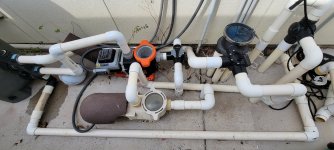
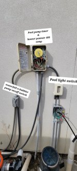
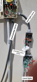
Waterfall n bubblersEveryone here is some extra pictures. I have 2 pumps 1 for pool n 1 for waterfall and jets. I hope this helps and thank you.
I posted some pics hopefully that helpsYou need to back away just a little and take another pic of the timer wiring so we can see where all those wires are routed.
Having said that, it looks like some of those white wires are used as jumpers. While I would use a different color, they will work. Also as said above, I would trim off the exposed copper a little to make a neater installation.
Art,
What does the timer itself control? ie: What does the timer turn on and off?
What model timer is this?
I am assuming everything you have runs off of 120 Volts AC.. Is that correct???
Thanks,
Jim R.
What does the timer itself control? ie: What does the timer turn on and off?
What model timer is this?
I am assuming everything you have runs off of 120 Volts AC.. Is that correct???
Thanks,
Jim R.
Last edited:
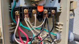
I hate to nitpick, but the new pic of the existing timer is a little too far away for me to trace the wires in the enclosure. 
Also it looks like the existing timer is a T104 which is a 240 volt timer and without knowing the model of the new one it's hard to tell for sure how it can be wired.
It looks like the installer used Black, White & Green wires to the equipment and Black, Red, ??? from the power feed?
At any rate, it looks like the light and the waterfall equip bypass the timer function and are hot all the time to the switches. The wires hooked to terminal "A" are just a junction point. Power is connected to "1" & "3" and "2" and "4" are the switched feed to the pumps.
Let us know if any of this is not correct.
thrystan
Active member
If those white wires really are hot and not neutral, you should put a wrap of black electrical tape around them near where they connect to the screw terminals. That is an indicator that even though the wire is white it's a hot wire not a neutral.
I hate to nitpick, but the new pic of the existing timer is a little too far away for me to trace the wires in the enclosure.
Also it looks like the existing timer is a T104 which is a 240 volt timer and without knowing the model of the new one it's hard to tell for sure how it can be wired.
It looks like the installer used Black, White & Green wires to the equipment and Black, Red, ??? from the power feed?
At any rate, it looks like the light and the waterfall equip bypass the timer function and are hot all the time to the switches. The wires hooked to terminal "A" are just a junction point. Power is connected to "1" & "3" and "2" and "4" are the switched feed to the pumps.
Let us know if any of this is not correct.


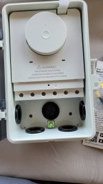
I hope this helps sorry I haven't had time to post here. Long days at work.. current timer is T104P3
Attachments
Here's a couple of things.
The new timer box doesn't have a non-dedicated terminal to terminate the wires that are under terminal "A" on the existing timer. However, you may be able to terminate them with some of the other wires.
Here's what I found out about the new timer.
The 'clock' terminals will accept up to 277vac, so you're good there.
The other 4 terminals are a copy of the 4 right terminals on the existing timer, so it should work as a replacement.
Hook the wires on the right 4 terminals wires on the existing timer to the right 4 terminals of the new timer maintaining the same placement (i.e. Wires on "1" go to "Com1", wires on "2" go to "NO1", etc., etc.).
Assuming that the wires under terminal "A" on the existing timer are L1, you can connect those wires to "L" on the new timer and then run a jumper from an L2 phase (either terminal "Com1" or "Com2") to the "N" terminal on the new timer.
If you are unsure of any of this you may want to hire an electrician or get a very electrically savvy friend to verify the connections for you.
P.S. I would use Wago connectors to make pigtails of all the multiple wires so you're only terminating one wire under each of the new timer terminals. You can also use wire nuts, but I love the Wago's. They make them for up to #10 awg wires (221-615).
Thank you! yes I think I will get one of my save friendsHere's a couple of things.
The new timer box doesn't have a non-dedicated terminal to terminate the wires that are under terminal "A" on the existing timer. However, you may be able to terminate them with some of the other wires.
Here's what I found out about the new timer.
The 'clock' terminals will accept up to 277vac, so you're good there.
The other 4 terminals are a copy of the 4 right terminals on the existing timer, so it should work as a replacement.
Hook the wires on the right 4 terminals wires on the existing timer to the right 4 terminals of the new timer maintaining the same placement (i.e. Wires on "1" go to "Com1", wires on "2" go to "NO1", etc., etc.).
Assuming that the wires under terminal "A" on the existing timer are L1, you can connect those wires to "L" on the new timer and then run a jumper from an L2 phase (either terminal "Com1" or "Com2") to the "N" terminal on the new timer.
If you are unsure of any of this you may want to hire an electrician or get a very electrically savvy friend to verify the connections for you.
P.S. I would use Wago connectors to make pigtails of all the multiple wires so you're only terminating one wire under each of the new timer terminals. You can also use wire nuts, but I love the Wago's. They make them for up to #10 awg wires (221-615).

Thread Status
Hello , This thread has been inactive for over 60 days. New postings here are unlikely to be seen or responded to by other members. For better visibility, consider Starting A New Thread.
Similar threads
- Replies
- 14
- Views
- 208
- Replies
- 1
- Views
- 39