Where to look for programming - Intellipro VSF and Intellitouch (old)

finsfanscott

Member
Feb 27, 2025
5
Orlando
Pool Size
12500
Chlorine
Liquid Chlorine
Hello everyone,

Purchased a home with older automation equipment. I have an Intellitouch panel inside and pretty sure an i5 outside (and a spa controller if that matters). Looks like firmware version 1.090 inside (UIC) and 1.160 outside (UOC).

I have an Intelliflow VSF pump. It is set up for External Control.

I have figured out how to change the programming for SPA (set up as egg timer for 3 hours), POOL (day/time) and HIGH SPEED (day/time, I'm assuming this is a custom set button) on the Intellitouch.

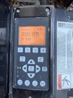
When I press the POOL button (or when its the correct time to run the POOL function) the Intelliflow pump will say "Prog 1" and will run at whatever speed I have set for Prog 1 in the setup on the pump. When I press the HIGH SPEED button (or the correct time for that function) the Intelliflow will say "Prog 2" and run at the (higher) speed I have set for Prog 2.

When I look at the programming on the Intellitouch, Menu-Setup-Equipment-Intelliflo- I have a screen of Intelliflo 4 pumps to select, but it appears there is nothing set up for any of the pumps.

While I can adjust the scheduled days/time on the Intellitouch, and the pump speeds (at least for Prog 1 and 2 under External Control) on the Intelliflow, how does the pump know to run Prog 1 for POOL and Prog 2 for HIGH SPEED?

I'm not looking to borrow trouble, since right now everything works, but the engineer in me wants to know! The previous owners left all the manuals but not sure how to decode any of the programing.

Welcome any thoughts or where I should look for this logic.

Thanks!
 
Scott,

The normal way for an IntelliFlo pump to be controlled by an IntelliTouch is via an RS-485 cable... This is not at all the same as "External control"..

External control just turns on a preset speed that is stored inside the pump.

RS-485 is a com port and all the speeds and scheduling is programmed inside the IntelliTouch.

I 'assume' your IntelliTouch can talk to your IntelliFlo, but wonder why it is currently set up for 'External Control. :scratch:

Let's see if Tom has any input based on your F/W version.. Calling @ogdento

What specific pump do you have?? I ask, because most older IntelliFlo pumps came with a two wire com cable... The two wire cable would not support external control.

How many wires are in your External control cable? How does it connect to your IntelliTouch?

Pics, would be great!!!

Thanks,

Jim R.
 
Sounds like your pump speeds are being controlled by relays in the Intellitouch and not by RS-485 digital comm between the panel and pump.

I suspect your Intellitouch firmware is old and does not have RS-485 VS pump support.
 
I don't know what "External Control" is in context of the Intellitouch... are you seeing that as an option in the pump setup?? send us a picture of your pump showing the Prog1/Prog2 etc.

Even though your outdoor board has 1.160, you're only going to see the options available in 1.090 since that's what's on your indoor controller. If you need to upgrade your firmware there's a thread on tfp for how to diy it, or pm me and I can assist.
 
Tom,

You can use relays inside the IntelliTouch to send 'external trigger' voltages to the pump... Not at all sure if that is how the IntelliTouch is being used or not..

We need pics...

Jim R.
 
Love this site and the replies. Thank you all for the intellectual curiosity. I will take pics tomorrow of the pump screen where I can change the External Control Prog 1/2 speeds and will take the cover off the outside panel and look for relays. Pretty sure @ajw22 and @Jimrahbe is/are on point with the relay controls, but don't know what/how to look for relays behind the panel. I'll be honest, I am VERY reluctant to upgrade firmware on old tech, as I have typically found the downstream effects to be less than gratifying, meaning I don't want to go down a rabbit hole of "this firmware version doesn't support that".

If you can't tell by now, I'm a Mechanical Engineer with no fear of taking (mechanical) things apart, but have a healthy fear of the electronic side of things!
 
  • Like
Reactions: Jimrahbe
Hello everyone, as promised here are some pics. And I have a greater (though not complete) understanding of what is going on.

First the pump pics - as shown, you can see the Intellipro VSF pump is set to run with "Ext Crtl" and receives on/off and speed commands from the newly discovered Intellicom Adapter via the RS485 cable shown:

Pump Ext Control.JPGPump Running Prog 2.JPGPump Signal Connector.JPG


After digging around the control panel, I found an Intellicom Adapter inside the i5 control panel. The Adaptater PRGM1, 2, and 3 twisted pair wires are wired to the "FLTR PUMP, AUX1, AUX2 outputs from the "top" control board, and an RS485 output that goes to the pump in the pic above:


Intellicom Adapter.JPGi5 Board Part numbers.JPG

So I still don't know the connection or programming protocol between the "POOL" and "HIGH SPEED" buttons on my Intellitouch and the PROG1 and PROG2 on the pump, but am getting closer! I understand the top board, the 520076 is a "Personality Module" but not sure how it is programmed or changed.

Thank you all for your thoughts and comments,
 

Attachments

  • Pump Prog 2 Set Speed.JPG
    Pump Prog 2 Set Speed.JPG
    557.6 KB · Views: 2
  • Pump Prog 2.JPG
    Pump Prog 2.JPG
    538.6 KB · Views: 1
Scott, @ogdento

On the surface, it does not make any sense to me. :scratch:

Why use relays to communicate with the VS pump, instead of using the com port on the IntelliTouch???

Please let me see pics of the relays in the Circuit breaker area of your IntelliTouch cabinet..

The question is... Do you want to screw with it or not??? :mrgreen:

What I would want to do is to connect the cable from the pump directly to the com port in the IntelliTouch.. The cable from the pump should only have two wires.. Green and Yellow. They would be connected to the corresponding Green and Yellow pins on the com port.

Don't do anything yet!!! And if you do, make sure all the power is off...

Please tell me where the wires that are connected to the 4 blue wire nuts go.. I suspect that they go to the IntelliCom 2 and your remote, but what else is connected???

Can you see the wire from the pump? If so does it have just two wires (Green and yellow)??

Thanks,

Jim R.
 
Yeah, that makes no sense to me either... I didn't think there was an "external control" setting at the indoor panel. What you've got is a pump that can talk to the intellitouch directly, but is instead going through the intellicomm... Which afaik was introduced to let you use an intelliflo pump on a non pentair system. What you have is very strange 😁. If you do want to screw with it and do what Jim suggested above, you should see "display not active" at the pump if it's being controlled by the intellitouch.

You can swap the personality module with an i7 i9 or i10 (they come in single or dual body - pool or pool and spa).
 
Thanks again for the thoughts:

1 - I certainly shut the power off before taking the panels off and taking the pics, don't want to let the smoke out of the wires.

2 - Wondering if they used the Intellicom because there are motorized Jandy valves that are automated as well (when I hit the SPA button on the Intellitouch, the valves move to drain/fill from the SPA instead of the main pool, and turns the heater on). Sorry I didn't mention this earlier. The Intellitouch also controls pool lights and a separate basin pump for a waterfall. There is also a spa side remote with buttons that mimic the Intellitouch inside the house.

3 - There used to be a SWG, but it doesn't work (according to the previous owners). Haven't messed with it yet to see if it is a bad cell, bad controller or somehow tied in to this setup. I have had a SWG in a previous pool, and know one only gets 3-4 years out of a cell in Florida. Just hasn't made it to the list yet.

4 - I can not see the wires in the pump, only the RS485 cable shown in the pic and main power connections in a conduit on the other side of the 485. The RS485 cable is connected to the Intellicom module.

5 - I will check where the COM blue wire nutted wires go. Typically what would go from an Intellitouch (inside my house panel) to the i5 panel mounted outside? A simple 4 wire connection like this or a larger bundle? Could these possibly go to the spa side remote?

As to whether or not I want to mess with it... I'm getting closer and closer to sitting on the fence, how much poking and prodding does one want to do with 15yr old automated pool systems? I know this stuff can get really expensive really quickly!
 

Enjoying this content?

Support TFP with a donation.

Give Support
Scott,

The Intellicom is just used to control the pump.. normally when you do NOT have an automation system... It has zero to do with the valves

In most systems... the IntelliTouch com port controls things like..

1. Pentair VS pumps
2. Pentair Remotes..
a. Wireless remotes via an antenna at the equipment pad.
b. Wired remotes via a 4 wire cable
3. Pentair Saltwater Chlorine Generators (SWCG)

You might want to think about upgrading to the new IntelliCenter with an upgrade kit.. The kit itself costs about $1,100 bucks, plus installation.

Personally, I'd be ripping it apart and removing the IntelliCom... Unless the previous owner can tell you why it is there.. If you take some good pics, you can always put it back together. It is really a pretty bullet proof system...

Thanks,

Jim R.
 
Thanks again for all the input.

Digging through some pool paperwork left behind, the Intellitouch controller was installed with the pool, filter and heater in 2007, along with a Max-E-Glas pump, I'm assuming it was a single speed pump.

In Jan 2020 the Intellipro VSF pump, Spa side remote and the "Intellicom II Intelliflo interface for automation" was installed, all on the same quote. Could it be possible that at the time of installation in 2020 the 2007 Intellitouch could not control a VSP so they had to add that module? If that's true, then why does the Intellitouch seem to have options for pump speed? Could the addition of the Spa side remote required the Intellicom module?

Went outside to get a better idea of the wiring:

From the attached picture below, from the Intellicom module to the i5 board:
Program 1 red and black twisted pair - to FLTR PUMP on i5
Program 2 twisted pair to - AUX 4
Program 3 twisted pair to - SPA

The COMM port on the Intellicom red and green appears to go to the pump through the thick black cable - would the pump only need two wires in the RS485 connection (pump has a separate power conduit attachment). The blue and red from Intellicom COMM port appear to be wire nutted together to the comm port on the 520076 board and wired with both the spa remote and Intellitouch- white being the spa side remote and the "bottom" blue going into the house. The "top" blue cable is attached to the GAS HTR port on the board, and indeed, goes to the heater!

At this point I am going to let this mess rest until something is really wrong with it, and just adjust time/schedules with Intellitouch in the house, and pump speeds at the pump.

But it remains curious to me why they would do it this way, since it appears the Intellitouch should be able to send a variable speed signal to the pump.
Holding the Intellicom.JPG


Thank you again -everyone- for your time and ideas!
 
Looks to me like the blue wire nuts are used to connect your indoor panel (UIC), Spaside remote, and possibly the intellichlor that you are not using - wire nuts instead of cramming too many wires into the comm port terminals. They could have installed the Comm Port Expansion Module instead.

The Intellitouch is sending analog signals (24vdc) from the Pool, Spa, and Aux4 relay ports to the Intellicomm2. The Intellicomm2 converts those analog signals to a digital signal which is sent to the pump via the black cable with the yellow and green wires (pump communication cable). The VSF pump should be wired directly to the breaker so it has power 24/7, waiting to receive digital commands from the intellicomm2. The intellicomm2 signal instructs the pump to run the speeds that are preset in the External Control section of the pump.

Curious - When you run High Speed from the indoor panel does it active Aux4 on the outdoor panel?

One important thing you could be missing is a higher speed when you are heating your pool. If the pool speed is set low for energy efficiency, there may not be the proper GPM supplied to the heater. With your current setup, you could correct this by installing a 4th jumper from the Elect Heat port on the Intellitouch to the Prog4 on the intellicomm. Then program External Control Prog 4 on the pump to a higher speed (RPM). If you did this, anytime the heater fires, the pump will run that higher speed.

Last thoughts - It's possible if you remove the intellicomm, and wire the pump data cable directly to the Intellitouch, you can make things work with what you have (1.090 inside). Even though you have the VSF pump, if you select Intelliflo4 in your Intellitouch settings, the VSF will still respond to the RPM commands sent by the Intellitouch. If you decide to try this I could verify if that works on my test systems in my shop.