Valve Actuator Mounting SOS

MyAZPool

Gold Supporter
Jul 3, 2018
2,296
Arizona
Pool Size
20500
Surface
Plaster
Chlorine
Salt Water Generator
SWG Type
Pentair Intellichlor IC-60
So, I was pre-mounting my IntelliValves today and there is an issue. This situation could occur with any valve actuator and I'm wondering if anyone has experienced the following.

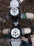
So when I re-plumbed this summer, I placed the Jandy valves too close to one another. Now if I mount the actuators correctly, the big part of one actuator gets in the way of the smaller section of the other actuator.

The only thing I can think of without doing some serious modification to the valves and/or the plumbing is this:

What would happen if I mount an actuator 180 degrees opposite from the correct mounting? Could I then reverse the red and white wire and would that solve the issue?

The other thing is if I could mount one actuator just above the other actuator in height. I would need a housing and spline extension I assume. Anything like this?

Anyone have any experience with this? Your help would be greatly appreciated (as always :))

Thanks in advance..
r.
 
Where's the picture???

lol.... That's a really good question and thanks for responding.
Yea, it's dark now, so in the morning, I'll get the actuators out and take some photos of the actuators near the valves. You will then be able to see that I am in a big pickle unless someone can help me get real creative :D...
Thanks again Brian!
r.
 
One thing I'm thinking about after spending some time at the workbench with an old Jandy diverter. In order to reverse the mounting of the actuator on the valve, is to use a Dremel to widen the one smaller slot in the Jandy diverter spline. Then set the spline 180 degrees opposite of the normal position. This would allow me to reverse the mounting.

I have discovered by reading the older actuator manual (CVA24), is that by adjusting the cams, one can mount the housing in any direction. That's certainly an advantage. The new valve is completely sealed and won't allow for that.
 
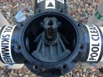
So the proper way to mount the actuator is for the large part of the actuator housing in which the cable is attached is to be mounted above where the "inlet" part of the valve is like so:

View attachment 88808

As you can see, when I attempt to mount the second actuator "properly", the housings of the two actuators get in the way of each other.

But if I can find a way to mount one actuator one way and the other actuator the other way, then no problem. The issue is if I do that then at the 0 position, I will be closing off the entire inlet which of course is a big "NO GO".

The actuator comes out of the box, set at 270 degrees. I'm thinking that if I first electrically (I will need to connect it up temporarily to the 24vAC connector on the IntelliCenter board) move the actuator 180 degrees to the 90 degree point, then I could mount the housing 180 degrees from normal. In a way, I'm kind of tricking the actuator to believing it is set at 270 degrees, where in reality it is set at 90 degrees. Then the problem is the 24 red lights will indicate opposite of the actual diverter position. Something I may need to live with. Or maybe I can reverse the red and white leads but until I experiment, I won't know if that actually works.

Another possible solution is to widen the small slot on the diverter spline and then mount the housing 180 degrees opposite from it's normal position.

View attachment 88813

View attachment 88811

View attachment 88812
 
r,

Not sure I fully understand what you plan to do, but keep in mind that when an actuator is normally set up the valve movement never shuts off the input flow.. If you mount it backwards, it appears to me that the valve will shut off the input pipe during its travel from one output port to the other.

If it was me, I would fire the plumber... :p

Thanks,

Jim R.

:laughblue:lol. Thanks Jim, I already have, but to no avail. He just keeps hanging around here getting me into more trouble. :p. Actually before I re-plumbed, I made the mistake of reading the CVA24 manual and took note of the fact that you could mount that actuator in any position on the valve by re-adjusting the cam settings inside the actuator. Then later, due to new info, I decided on the IntelliValve. Woops!. With the intellivalve, the only adjustment is electrically from 90 degrees to 270 degrees (compass position). So, I would highly advise anyone considering a new pool (or in my case, a re-plumb) who intends to use multiple IntelliValves, now or in the future, to mount the Jandy (or similar) valves in the plumbing makeup, at least 8 to 12 inches from one another and from any other tees or ells if they will interfere with the mounting of the actuator!

So, yes you are correct, but I think that if I electrically move the actuator from 270 degrees to 90 degrees FIRST, then place the actuator on the valve spline 180 degrees from it's normal mounting, then when it tries to move back to what it thinks is the 270 degree position of the valve, it will actually be moving the valve back to 90 degrees WITHOUT the valve diverter transversing the actual valve inlet. (I think).

I will play with this and keep you informed but I have bigger "fish to fry" at the moment before I can even have the ability to electrically connect the valve. I first have to swap the old IntelliTouch System Transformer out with the new IntelliCenter System Transformer in the load center (which I am in the middle of). Its a pain in the rear but certainly doable, just time consuming. Then mount, connect and power up the IC and then run through the set-up wizard. That will at least get me to the minimum point where I can power up an IntelliValve.

Fun and games sir...
r.
 

Enjoying this content?

Support TFP with a donation.

Give Support
Not sure this will help at all but the Jandy JVAs have a switch on them to reverse the direction. It is a 3 way switch that toggles between forward, stop and reverse.
 
I like the idea of modifying the valve spline and I don't see why that wouldn't work.

If all else fails you can always swap one of the Intellivalves with a standard actuator and place that on the valve that you only need two position adjustability...probably not nearly as cool as having a digital display to tell you where your valve is but at least it would accomplish what you need it to do

- - - Updated - - -

I'm not able to see the attachments :scratch:

Unlike Jim, I was hoping to give compliments to your plumber :poke:
 
Brian,
Correct. No way to take the valve apart that I can see. I see you are "in the industry'", so maybe you have some additional information that I don't know about. If so, please share. ;). Thanks!! r.
 
I like the idea of modifying the valve spline and I don't see why that wouldn't work.

If all else fails you can always swap one of the Intellivalves with a standard actuator and place that on the valve that you only need two position adjustability...probably not nearly as cool as having a digital display to tell you where your valve is but at least it would accomplish what you need it to do

- - - Updated - - -

I'm not able to see the attachments :scratch:

Unlike Jim, I was hoping to give compliments to your plumber :poke:

Brian,
Sorry for the delay in responding, but I've been a busy guy last few days. First things first, I had to change out the system transformer and two of the low voltage circuit breakers in the load center. Next, install the IntelliCenter Personality Board and Valve Expansion Board. Then, system configurations, basic "circuit", "features" and "pump" configurations, just so I could keep Mr. Pool going. :grin:

A few minutes ago, I connected a valve to the board and proceeded in testing my theory of moving the valve actuator position 180 degrees from it's factory start position and then positioning it on the valve 180 degrees from normal mounting. FAILED. Jim R. was correct as usual. What happens, is the diverter then transverses the INLET position (not good). Everything is based on that smaller width groove on the spline of the valve diverter.

So tomorrow morning, I will test my second theory in which you commented on. I've got some spare diverters, so I will try to hollow out the smaller groove on the valve diverter spline, install it on a valve, connect up the actuator to 24vAC and start playing. I'll let you know.

p.s.

Not sure why you can't see the photos. Maybe one of the forum guru's can shine some light on that one. They are way ahead of me as to figuring those things out.
Hopefully you can give a little credit to the "plumber". :laughblue:

Thanks for your interest and support.
r.
 
I like the idea of modifying the valve spline and I don't see why that wouldn't work.

Brian.
That was the ticket! :whoot: The valve diverter will traverse the 180 degree range of the valve correctly by widening the small groove in the diverter spline and then mounting the actuator 180 degrees opposite from it's normal/correct mounting. The only downside to this method that I can see at this point, is that the lights on the actuator are reversed from where the actual valve diverter is located within the valve housing. I can live with that. Sure beats a re-plumb.

59.jpg

I'm now wondering if I could reverse the lights in the actuator by reversing the two +/- 24vAC wires? Any thoughts?

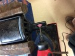
Here is how I widened the small groove in the diverter spline. I used a dremel tool.
IMG_4691.jpg

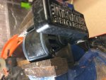
As you can see then (hopefully these photos show up), The handle will fit on the diverter spline 180 degrees opposite from it's normal position.
IMG_4693.jpg

IMG_4695.jpg

Then I placed the diverter in it's "zero" position within the housing and electrically moved the actuator to it's "zero" position and then placed the actuator on the valve 180 degrees opposite as indicated below.
IMG_4696.jpg

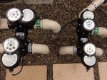
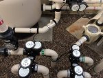
The end result is that both actuators will now fit together on the intake/suction manifold make-up. Now I get to do this one more time for the return manifold (actually twice since this one was a old "test" diverter that's been lying around).
Actuators.jpg

Would be great if anyone knows whether reversing those two power wires will result in reversing the lights. Thanks....
r.
 
I would imagine the lights have less to do with the wiring and more to do with an internal contact on the diverter rotator. Try plugging the actuator connector into the socket backwards - you'll probably have to grind those little nubs off the connector to get it in there...
 
I would imagine the lights have less to do with the wiring and more to do with an internal contact on the diverter rotator. Try plugging the actuator connector into the socket backwards - you'll probably have to grind those little nubs off the connector to get it in there...

Thanks much Brian...
So I tried that (thanks for the tip), but the valve actuator did not like having the red and white power wires reversed. The actuator would not power up.

So I will just live with 3 out of 6 actuators being mounted in reverse. No biggie, I just have to get used to it. I think I will make some pencil marks or similar where the normal everyday valve positions (filter mode) should be because it's a little goofy watching the lights go one way and imagining the valve diverter going another :D. Once I set the home and second position and program the IntelliCenter, reference the actuators, then I shouldn't really have to worry about it too much.

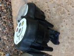
Here are a couple of photo's showing the final mounting/installation of 4/5 of the 6 IntelliValves. Tomorrow, it's on to finalizing all the actuator wiring and then on to connecting up the wiring from the "Firemans Switch" on the heater to the IntelliCenter Control System Circuit Board. :confused:

Thanks again!
r.

IMG_4704.jpg

IMG_4705.jpg
 
There's a jumper in your heater wiring that you cut and tie a 2 wire cable to the gas heater terminal on the IC board.

All the IC does is connect the circuit when demand for the heater is called for.

Thanks Brian! Actually, I haven't got to the heater yet, but I will :D. I played around with the IntelliValve actuators today. I learned a lot about these actuators while discovering their capabilities and getting 5 of the 6 programmed (I just haven't got around to mounting or connecting the heater bypass valve actuator yet, but it will be a piece of cake since it will mount correctly.) :)..

So, I had made the comment that it was difficult for me to imagine just where the valve diverter actually was in relationship to the lights reference the actuators that were mounted opposite from their normal mounting. Issue resolved. For those particular 3 actuators that are mounted backwards, I just use the lights to tell me where the Jandy valve HANDLE would be. Once you look at it like that, then imaging where the diverter is within the housing, is pretty easy and makes sense to me. For those 3 actuators, I will just label them "HANDLE" and the other 4 "DIVERTER".

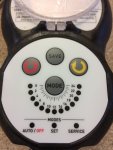
While fooling around with the actuators, I discovered that although there are 24 lights, there are actually 48 positions. The diverter within the valve housing moves 3.75 degrees for each push of the RED or YELLOW arrows. You can select any of these 48 positions as the home and second saved positions. While fooling with them, I found that the positioning of the valve diverter was actually more precise using the actuator, then when I would position the valves manually by using the valve handle.

IMG_4708.JPG

This actuator is pretty easy to use and kind of fun to play with. I found the programming of the HOME and second position fairly intuitive and straight forward once you do it once or twice. The instructions in the manual, not as much. They could have simplified the instructions a bit I think.

Basically you just press the MODE button until the blue SET light illuminates. Move the RED arrow to the first position that you want to save and press SAVE. Then move the RED button to the next position that you want to save and press SAVE. Press the MODE button until the green AUTO light illuminates. The actuator will move the valve to the first saved position. If you want home to be the other saved position, then just press the RED and YELLOW buttons simultaneously while in the AUTO mode and the actuator will move the valve to that second position and consider it HOME. That's it basically.

SERVICE
mode is used to change the valve position to any other position other than the two saved positions.

I was going to time how long it took for the actuator to move from it's zero position 180 degrees to the 24 position, but I spaced it. It's probably about 20 to 30 seconds or so, but if I remember, I will check that out.

I used HOME as my everyday normal "pool" filter mode setting and my second position as my "spa" use, water feature, or bypass setting. I recorded my HOME and second position on paper for each valve using increments of .5, i.e. For my Intake/Suction valve, Home=21.5, Spa=12.0.

I devised a chart that kind of illustrates the movement of the valve and its positioning each time one of the arrows are pressed. Looks kind of stupid I know, but it helps me to understand the positioning of the diverter in relationship to the indicator lights.

2018-12-02_21-57-53.jpg

Thanks much!!
 
My,

One of us has way too much idle time on their hands... and I'm the one that is retired... :bounce:

Once you get your system up and running, you will find that valve accuracy is about the same as grenade accuracy... anything close, is close enough..

Nice work by the way,

Jim R.
 

Enjoying this content?

Support TFP with a donation.

Give Support
Thread Status
Hello , This thread has been inactive for over 60 days. New postings here are unlikely to be seen or responded to by other members. For better visibility, consider Starting A New Thread.