Upgrading to Suraielec Wifi Box Timer Switch

usmc13

New member
Mar 26, 2022
2
Key West, FL
Hi all,

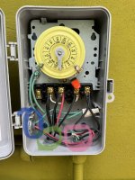
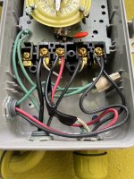
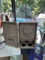
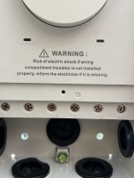
I'm wondering if anyone might be able to help me. I currently have an old Intermatic Pool Pump timer and purchased a Suraielec Smart Wifi Timer Switch. After spending and a bit amount of time looking over the instructions and wiring diagram I'm a little stumped. Right now, we have a salt chlorinator, pool pump, and the heater tied to the Intermatic timer.

Blue circle: Salt Chlorinator
Green circle: Pool Heater/ breaker box
Pink circle: Pool Pump

I appreciate anyones feedback/help!

Zach
 

Attachments

  • IMG_4398.jpg
    IMG_4398.jpg
    459.3 KB · Views: 183
  • IMG_4399.jpg
    IMG_4399.jpg
    437.8 KB · Views: 163
  • IMG_4400.jpg
    IMG_4400.jpg
    508.9 KB · Views: 110
  • IMG_4401.jpg
    IMG_4401.jpg
    331.2 KB · Views: 113
  • IMG_4402.jpg
    IMG_4402.jpg
    340.8 KB · Views: 135
WElcome to TFP.

Follow lower left diagram 4.

The new timer schematic shows 6 terminals L, N, com1, no1, com2, no2
existing timeclock screws are 1, 2, 3, 4

move wires as follows:

1 wires go to com1
2 wires go to no1
3 wires go to com2
4 wires go to no2

Now you need to power the timer on L and N. Take the wire on com1 and wire nut it together with two pigtails. One pigtail goes to L and the other back to com1.

Do the same for the wire on com2 and connect its pigtail to N.

Wire nut all the green wires together and they don't connect to the switch.


cd659ae4-8ac5-4c35-9b32-c5fed80c206f-__cr0-0-970-600_pt0_sx970_v1___-jpg.366373

1
 
Last edited:
  • Like
Reactions: usmc13
WElcome to TFP.

Follow lower left diagram 4.

The new timer schematic shows 6 terminals L, N, com1, no1, com2, no2
existing timeclock screws are 1, 2, 3, 4

move wires as follows:

1 wires go to com1
2 wires go to no1
3 wires go to com2
4 wires go to no2

Now you need to power the timer on L and N. Take the wire on com1 and wire nut it together with two pigtails. One pigtail goes to L and the other back to com1.

Do the same for the wire on com2 and connect its pigtail to N.

Wire nut all the green wires together and they don't connect to the switch.


cd659ae4-8ac5-4c35-9b32-c5fed80c206f-__cr0-0-970-600_pt0_sx970_v1___-jpg.366373

1


Thanks so much for your help! I'm not as handy as I'd like to admit. This literally took me 20 mins to disconnect the old one and wire the new one. First try, it powered up and everything is working perfectly. I appreciate your help!
 
Diagram 4 above indicates that the power supply to the timer is 240V. Is this correct?

Yes.
I was expecting that the timer supply would be a 120V using the load from one phase of the 240V input on L and the neutral wire connected to N.
Some all 240V setups are not wired with a neutral to use for 120V.

The timer electronics is dual voltage 120/240V.
 
Thread Status
Hello , This thread has been inactive for over 60 days. New postings here are unlikely to be seen or responded to by other members. For better visibility, consider Starting A New Thread.