Trying to figure out my X10 pool automation

coilerman

0
Bronze Supporter
Sep 29, 2008
169
Toronto, Ontario, Canada
I'm looking for a little bit of guidance and confirmation on how my existing pool automation works. I've posted about this before but gave up due to the complexity. I'm trying again to understand how this works. Not expecting all the answers here but hopefully someone can help shed some light.

I have an X10 system that has three functions:

A) Spa:
1) turns on booster pump (240v)
2) triggers spa mode on heater (low voltage remote switch)
3) actuates a pair of Goldline GVA-24 valves (24v)

B) Spa light

C) Pool light

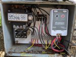
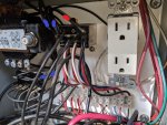
All this magic occurs inside this metal box:

110557

My questions:

1) Is it correct to assume that the Relay A is controlling the 24v equipment and the Relay B is controlling the 240v?

2) The lead from the X10 Universal Module appears to be connected in series to Relay A and Relay B. Would these relays be X10 specific devices? Looking through X10 websites and I don't see anything similar.

3) I'm assuming the transformer is there to convert 240v voltage to 24v and would be connected to Relay A.

4) What's the purpose of the circuit breaker (white button with "4"), if that's what it is?

Any comments are appreciated.
 

Attachments

  • InkedIMG_20190710_105819_LI.jpg
    InkedIMG_20190710_105819_LI.jpg
    235.9 KB · Views: 3
Just to make the wiring a little clearer, can you take a couple of pictures with the flash on and a couple different angles?

1) Correct, Relay B controls the 120/240 volt loads (pump & Light).
2) They're most likely paralleled, but I can't trace the wiring well in the picture. But, they're not X10 devices. Relay "A" looks like a 4 pole double throw and relay "B" looks like a 4 pole single throw.
3) Correct. That's the 24VAC power for the valves, etc..
4) That's a circuit breaker. I can't tell whether it's on the primary side of the transformer or not, but it probably is.
 
C,

The transformer's job is to reduce the 240 to 24 volts AC. It is providing power to the X10 modules as well as the valves and I think the power to turn the relays on/off. Edit.. I thought that the two wires at the bottom of the X10 were for the operating input voltage, but it is really the output from a SPST relay...

The button with the red "4" is a circuit breaker and it will open if too much currently is used.

I think you are basically right at the low voltage relay and the high voltage relay, but it is very hard to tell what is what based upon the picture.

I am not certain we can see everything, as it does not make sense on the surface.

Do your Spa light and Pool light come on at the same time? If not, that would require two relays...???

Does your booster pump run when the lights are off? That would require another relay???

I see no GFCI protection for the lights, so not sure what is going on with the lights???

I see no relay for the heater, so maybe inside the X10 module???

Tell us more and we might be able to come up with more comments.

What is your overall plan??

Thanks,

Jim R.
 
Last edited:
Do your Spa light and Pool light come on at the same time? If not, that would require two relays...???

They are separately controlled. There are three buttons on the X10 controller - 1) spa, 2) pool light 3) spa light. See my note below about the lights.

Does your booster pump run when the lights are off? That would require another relay???

Yes it does. I can turn off the lights and the booster works.

I see no GFCI protection for the lights, so not sure what is going on with the lights???

I think I figured out the light part - they are on separate circuits that have X10 switches so they are not controlled from this box at all.

I see no relay for the heater, so maybe inside the X10 module???

The heater remote wire is the big red wire at the bottom right. It's connected to the wiring block that's then connected to Relay A.

What is your overall plan??

I want to add additional functionality.

1) Remote operation. I want to be able to switch to spa mode while on my drive home so the spa is nice and hot when I arrive.
2) I would like to add remote control capability for my pump. I have a Pentair Superflo VS and I am planning to purchase the remote cable so I can switch speeds.

I have some understanding of Arduino based automation so I'm wondering A) do I rip out the existing X10 stuff and start from scratch or B) piggyback on it to add the functions I want. I think the simple solution is to find an Arduino module that mimics the X10 Universal module and simply control the existing relays.

Here are some additional photos. In the first one, I've color coded some of the wires coming out of Relay A. The blue one goes to the back of the circuit breaker. The two green ones connect to Relay B. The red ones go to the X10 Universal Module.

Also, I've added photos of the labels on the two relays.

110628


Relay A:
110635

Relay B:
110634

110636
 

Attachments

  • IMG_20190711_164150.jpg
    IMG_20190711_164150.jpg
    213 KB · Views: 3
I'm not Jim, but my 2¢ is that given what you want to do, I'd rip everything out and replace it with an Arduino relay board. That way you could program the valves and equipment the way you want it to work.

You'll need four relays for the pump, so you could get an eight relay board and use the rest of the relays to operate the valves and heater, etc..
 
Thanks for the extra pics, but I still don't understand how things work if you only have two relays.. :scratch:

I'm not Dave, but I agree with him completely... I would not try to add to what you have.. I would install a new system.. In my case I would be looking for a manufactured unit rather than something I needed to build from parts, but that is just me.

Jim R.
 
I was wrong about relay "B". it's a double pole single throw. That just means that it has two sets of normally open contact sets.

I'll draw a schematic of the circuits next week if you'll remind me.
This is pretty common X10 control.
They're using the x10 relay to fire the relays, which switch the valves and turn on the pump and lights.
You'll notice that all the commons on relay are soldered together. This is 24v hot from the transformer.
Then they take a wire off the end of that row to the X10 relay. That is how they switch the relays on.
The X10 relay switches relay "A" on when called for, and relay "A" switches relay "B" on through the set of contacts on the left.
On relay "A" the second and third contact sets have a red wire on either the N.C terminals (I think that's right) and a white wire on the N.O. terminal of that contact set. That powers the valve actuators one way when the relay is off and the other when the relay is on.
Then relay "B" just makes the power to the pump and the lights through it's contacts when energized.
 
Dave,

I agree that relay B is a DPST, just like the relays in my EasyTouch..

What I want to know is how he is able to turn on the lights and booster separately with the same relay???

On the surface, it makes no sense.. :scratch:

Jim R.
 

Enjoying this content?

Support TFP with a donation.

Give Support
The lights are not part of the system. They are controlled by separate X10 switches. I found that out after my original post while I was tracing the wiring.

OK... That makes a lot more sense to me now... So the set up you have in your pics only controls the booster pump (B relay) and your valve positions (A relay). The A relay may also turn on the heater, but I am not sure about that yet...

Thanks,

Jim R.
 
Well, as I promised. I made a shot at a wiring diagram.
If you see anything that doesn't look right, let me know and we'll try to fix it.

111307

P.S. don't take back what you said about Nick. Most of it's probably true! :)
 
This is great and looks accurate. Thanks so much. What software do you use for this?

The X10 Universal Module is simply a low voltage relay itself, is it not? It's taking 12v from the transformer and when the contact is closed, sending it to Relay A. Could I just replace that with an Arduino controlled relay and leave everything as-is?
 
Last edited:
Thanks, I use AutoCAD or one of a couple of replacements (Sketchup, NanoCAD).

You'e right, the universal module is just a relay that pulls in a single set of contacts. You certainly could use an Arduino relay and leave everything as-is.

You could even use a smarthome device (Alexa, google home, apple homekit, etc.) to control it if you have a preferred platform instead of using Arduino.
 

Enjoying this content?

Support TFP with a donation.

Give Support
Thread Status
Hello , This thread has been inactive for over 60 days. New postings here are unlikely to be seen or responded to by other members. For better visibility, consider Starting A New Thread.