Thinking of making the switch - Installation questions

J,

Close, but no cigar... :mrgreen:

I need to know which physical relay is connected to which main board port..

I am pretty sure that the Pump/Filter port is connected to the Aux 1 physical location.

Which relay is connected to Aux 1, Aux 2. and Aux 3 ports??

Jim R.
Jim

Did you see my most recent reply. I narrowed it dow further and color coded on the picture. Does that help or am I still missing something?
 
  • Like
Reactions: Jimrahbe
Ok,

I now understand how everything is wired.

If you look at the relay being used as the Pump/filter relay (in red box) you can see that the line or input pins have two wires. These two wires provide constant AC power to the IntelliFlo pump. The Load or output pins only have one blue and one red wire. I suspect that these wires are going to your UV system. You will need to follow them and make sure that is where they go.

To install the new SWCG transformer, you'd remove the current blue and red wires and cap them off. This will leave the two load pins empty. Now you can connect the White and Yellow SWCG transformer wires to the empty load pins.. This will only let the SWCG transformer turn on when the pump is being told to run.

Thanks,

Jim R.
 
  • Like
Reactions: jlamb5990
Ok,

I now understand how everything is wired.

If you look at the relay being used as the Pump/filter relay (in red box) you can see that the line or input pins have two wires. These two wires provide constant AC power to the IntelliFlo pump. The Load or output pins only have one blue and one red wire. I suspect that these wires are going to your UV system. You will need to follow them and make sure that is where they go.

To install the new SWCG transformer, you'd remove the current blue and red wires and cap them off. This will leave the two load pins empty. Now you can connect the White and Yellow SWCG transformer wires to the empty load pins.. This will only let the SWCG transformer turn on when the pump is being told to run.

Thanks,

Jim R.
Perfect. And just to clarify too, the black wires running out of the line side, those are just connecting the line side to the actual breaker in the panel right? So that it controls the power on/off to that relay?

The UV is on the same breaker (sort of, it’s one of those breakers where there is two 20amp breakers, but they are one solid piece so the switch powers on both the pump and the UV, sorry I don’t know what that’s called in the electrical world). If I disconnect the load wires and cap them for the UV at the relay, would I also have to disconnect and cap the wires at the breaker for the UV? Then is it safe to leave the Pump/Filter breaker as the only one that has wires going into it? Or do I need to get a new single 20amp breaker for the pump wires too?
 
J,

The very top breaker currently powers both the pump and the UV system with 240 volts AC power. Each half of the breaker provides 120 volts, but because they are out of phase with each other, the total voltage is double or 240 volts. You can see the two black wires leaving the breaker and going up to Line input pins of what is being used as the Pump/Filter relay. Also attached to the line input pins are blue and red wires that go directly to the pump. This provides constant 240-volt power to the pump. The power going to the pump does not go through the relay. When the pump/filter relay closes, the 240 volts on the line input pins also goes through the relay out the load pins on the blue and red wires going to the UV system. The UV system also runs off of 240 volts AC.

Basically, you are just going to replace the two wires that are now going from the Pump/Filter relay to the UV system with the two new wires that will be coming from the input side of the new SWCG transformer. The breaker does not change.

Keep asking questions until this makes sense.

Jim R.
Got it. I think that makes sense. So the two black wires are giving power to the pump and then that power is almost being continued to the UV via the load outputs on that relay. What I’m doing is just removing those UV wires and replacing with the SWG wires so the power continues to the SWG instead of the UV. (I think?!)

So when I remove the UV wires and cap them, they remain in the panel forever? They won’t just pull out of the panel entirely once I remove the UV? I assumed all those wires would just feed out the bottom pop out on that panel and through the conduit?

All great info and really appreciate it
 
When you remove the conduit for the UV, make sure you install a knockout seal, or hole seal to prevent wasps (or other insects) from nesting in your control panel.


Your local home center/box store/hardware store should have something similar.

--Jeff
 
  • Like
Reactions: jlamb5990
When you remove the conduit for the UV, make sure you install a knockout seal, or hole seal to prevent wasps (or other insects) from nesting in your control panel.


Your local home center/box store/hardware store should have something similar.

--Jeff
Thanks! I probably would have just put tape but there’s no reason to get 99% there on this project and cheap out at the end. I’ll make sure to grab one!
 
@Jimrahbe

Jim

Think I may attempt this on my own with advice you’ve given. I do have one more question I don’t can’t understand. Going to break down my thinking and see if this is right

1 So the transformer wires plug into the load side of the pump relay which give power to that transformer
2 the surge card in the upper compartment is currently plugged into the grey breaker on the intellichlor
3 the other end of the surge card clips into they grey connectors and runs down the left side of the panel ending at the intellichlor plug on the bottom
4 the intellichlor gets plumbed in and the power cable plugs into the bottom of the panel

My question is…where is the intellichlor actually getting is power from? Are there other wires from the transformer besides the green and yellow that need to be wired into something? Or does the surge card up top provide power via the pump/ filter relay. Trying to understand if the load outputs are sending power only to the transformer, how is the intellichlor cell getting its power? Also, What’s the point of the grey intellichlor breaker in the upper compartment then?

Sorry for the barrage of questions. Just trying to make sure I really understand this all before I start messing with it (if I decide to)

Thanks
 
My question is…where is the intellichlor actually getting is power from? Are there other wires from the transformer besides the green and yellow that need to be wired into something? Or does the surge card up top provide power via the pump/ filter relay. Trying to understand if the load outputs are sending power only to the transformer, how is the intellichlor cell getting its power? Also, What’s the point of the grey intellichlor breaker in the upper compartment then?
Think I may have found it. There is a red wire on the other side of the transformer that runs needs to be run to the upper panel and plugs into the ac port on the surge card. Is that correct?
 

Enjoying this content?

Support TFP with a donation.

Give Support
J,

There are two wires from the output side of the SWCG transformer. One of them plugs into the input to the small grey circuit breaker and the other plugs into one of the AC inputs to the Surge card. Basically, current flows from the one leg of the transformer's output, through the grey circuit breaker to the Surge card, through the Surge card and back to the other output leg of the SWCG transformer.

You can see the two AC inputs to the Surge card in this pic..


Do you already have the new SWCG transformer for your system?????


Thanks,

Jim R.
I ordered it yesterday and will be delivered next Wednesday. I think im going to pull the trigger on the salt cell too. I can get it from Amazon for $860 delivered next week. Then its just on to the plumbing!
 
Looks like the grey breaker on mine is already plugged into the ac port. So all I need to do is run one more red ac wire to the spot I circled right?
 

Attachments

  • B5C048CA-B9A1-4CC1-B5D1-3EFD779DC54A.jpeg
    B5C048CA-B9A1-4CC1-B5D1-3EFD779DC54A.jpeg
    313.2 KB · Views: 11
This is my plumbing plan. Let me know if you see anything problematic. Obviously remove the UV and tab feeder but basically follow the line out the heater but where it connects into UV currently I want to turn that 90 vertically to go up to the level of the actuator and returns. Put another 90 to start horizontally again. Then put the SWG on that horizontal run. Picture doesn’t really show perspective too well but gets the point across. Let me know what you think.
 

Attachments

  • 156F85BD-612A-4CA4-9255-CBD462723B0F.jpeg
    156F85BD-612A-4CA4-9255-CBD462723B0F.jpeg
    457.7 KB · Views: 14
Looks like the grey breaker on mine is already plugged into the ac port. So all I need to do is run one more red ac wire to the spot I circled right?

Yes, the grey breaker's output is connected to the Surge card already. The SWCG transformer has two output wires.. One has to be connected to the input side of the little grey breaker and the other has to be connected to the AC input to the Surge card that you have circled in red.

Your plumbing plan looks just fine to me...

Thanks,

Jim R.
Got it! I didnt realize there was an input side to that grey breaker. Good to know!

Just ordered the Ic40 from amazon...$850 shipped which is nice.

Is there anything that i should be aware of for install? Ive read things about dummy cells, flow switches and bypass lines but not sure how they all play into my situation, if at all.

Also, is there anything i need to do to drain the lines before cutting the UV and feeder out? Is that done through the pool draining spigot located after my pump or do i need to drain at the cartridge filter as well?
 
J,

I suspect that you will have to drain everything.. I'd just take this as an opportunity to drain and clean the filter, etc.

Basically, you will be cutting the pipes at the bottom of your equipment pad. Anything that is higher will just drain down and out the open pipes.

You would do this with the pump off, so no reason to use the spigot at the pump for anything.

Thanks,

Jim R.
 
  • Like
Reactions: jlamb5990
J,

I suspect that you will have to drain everything.. I'd just take this as an opportunity to drain and clean the filter, etc.

Basically, you will be cutting the pipes at the bottom of your equipment pad. Anything that is higher will just drain down and out the open pipes.

You would do this with the pump off, so no reason to use the spigot at the pump for anything.

Thanks,

Jim R.
Hey Jim

Just got both the transformer and IC40 in the mail today. So the install is probably being attempted sometime this week. Any final words of wisdom beyond the wiring and plumbing you walked me through?

Should I add all my salt I need before installing the SWG? What’s the best way to test my current salt levels and what salt is best to use to get me to 3000ppm? Also my CYA is at 60 right now. Do I need to bump that up?

Finally, after wiring in the ic40 to the pump relay, are there any precautions to take with it running? Do I need to install a check valve between my heater and the cell or is that already built in? I’ve also heard people talk about dummy cells and bypasses for certain times? Is that needed or could I just turn off the power or lower the % to 0 on screenlogic and have water run straight through without being chlorinated? Any other precautions to be aware of I’m missing.

Thanks again for the help with all this.
 
J,

You do not need a check valve between the SWCG and the heater. That check valve is only required if you have a tab feeder.

I have three saltwater pools and do not have a by-pass or dummy cell. I can't think of any reason to have them.

In the winter you just set the output to zero. In my case I have separate circuit breaker for the SWCG power supply, so I just shut it off in the winter. This is not the same as the small grey breaker that you never want to try to turn off.

I would not add any salt until the water temp gets about 55 degrees on constant basis.

Your pool most likely has a lot of salt in it right now. I recommend you get a Taylor K-1766 salt test kit. You need to have the ability to measure the "actual" salt level vs. what the cell reports, which can be way off.

Pool math will tell you how much salt to add. You enter what your pool currently has, and pool volume, what your salt target is, and it will tell you how much more you need.

CYA of 60 is fine in the winter. I would not worry about getting it up to 70 until the summertime.

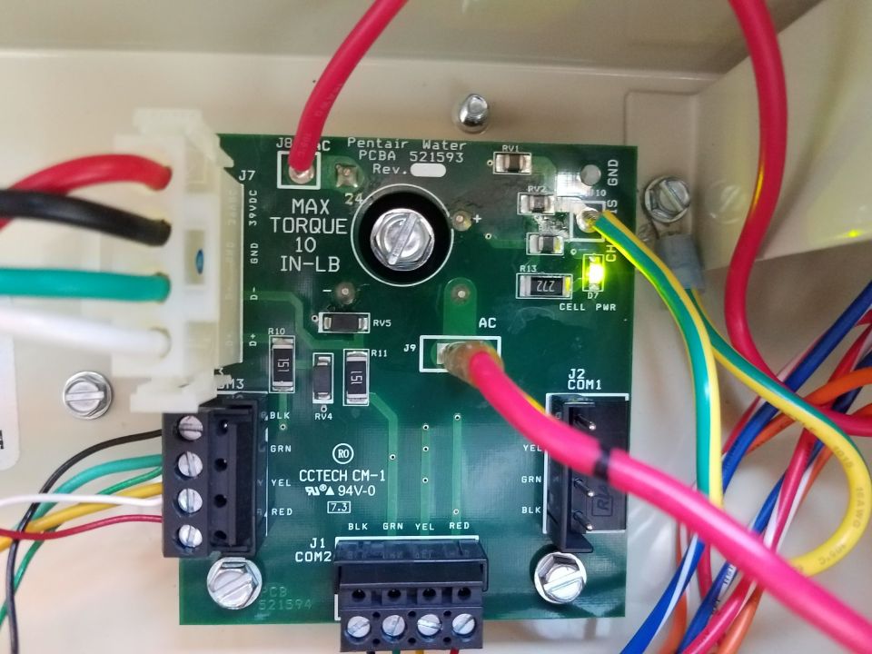
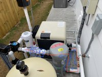
You might want to post a couple of pics of your install wiring before firing it up.. :mrgreen:

Edit.. You will need to tell ScreenLogic you have a SWCG so that it shows the following page..


View media item 1963

Thanks,

Jim R.
 
  • Like
Reactions: jlamb5990

Enjoying this content?

Support TFP with a donation.

Give Support
Thread Status
Hello , This thread has been inactive for over 60 days. New postings here are unlikely to be seen or responded to by other members. For better visibility, consider Starting A New Thread.