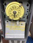
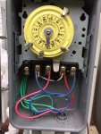
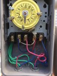
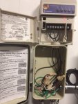
Even though, the licensed electrician should know this, I was just curious if anyone knows how the SWG Control Box is wired into the Intermatic Timer. He will be here in a few days to hook up the heat pump. Below are some pictures.
I picked this up on line, on how the SWG is configured.
• 240 Volts AC- Green to ground and 2 red wires to # 1 and # 4
• 120 Volts AC Loosen # 2 and # 3 and remove the 2 stack jumpers and move one jumper up and one jumper down. To apply 120 volts AC, attach 2 wires, normal black and white or red and white to terminals 1 and 4. Aqua Rite on left side and Pro on right side.
• Connect SWG # 8 bare wire to bonding on bottom on control box. Bonding system bare wire – bottom on SWG cabinet. Bonding wire to of plumbing wire.
Now, there should be a total of 3 wires. Anyone know how they are set up. Pictures of timer put together.


Left side is power to fuse box with shut off switch and the right goes to the 2 HP Hayward Pump.
I picked this up on line, on how the SWG is configured.
• 240 Volts AC- Green to ground and 2 red wires to # 1 and # 4
• 120 Volts AC Loosen # 2 and # 3 and remove the 2 stack jumpers and move one jumper up and one jumper down. To apply 120 volts AC, attach 2 wires, normal black and white or red and white to terminals 1 and 4. Aqua Rite on left side and Pro on right side.
• Connect SWG # 8 bare wire to bonding on bottom on control box. Bonding system bare wire – bottom on SWG cabinet. Bonding wire to of plumbing wire.
Now, there should be a total of 3 wires. Anyone know how they are set up. Pictures of timer put together.


Left side is power to fuse box with shut off switch and the right goes to the 2 HP Hayward Pump.


