- Jun 7, 2017
- 9,998
- Pool Size
- 29000
- Surface
- Plaster
- Chlorine
- Salt Water Generator
- SWG Type
- Jandy Aquapure 1400
I have no experience with FloPro, but agree this is strange. Wonder if the pump is wired like a single speed with power controlled by the pump relay. I looked at the manual. It's supposed to have continuous power just as every other VSP I've seen. I don't see how it would ever switch off with continuous power, since the RS-485 link doesn't seem to be configured.I hope the OP can follow the set up for the Jandy pump Starting on the screen you shown. it is weird that the OP has a schedule for a pump but the pump is not set up in the VSP setting screen.
I have no experience with FloPro, but agree this is strange. Wonder if the pump is wired like a single speed with power controlled by the pump relay. I looked at the manual. It's supposed to have continuous power just as every other VSP I've seen. I don't see how it would ever switch off with continuous power, since the RS-485 link doesn't seem to be configured.
It looks like just 2 wires plus a ground. They are inside the conduit running from the pump to the AquaLink panel.
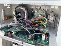
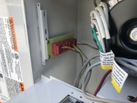
I still am not sure you have your VSP set up properly yet. Did you ever confirm if you have a 4 wire cable going from the VSP to Aqualink?
To select a speed for the scheduler, you'll need to do the following (within the scheduler):
Select "VSP1 Spd Adj", then select speed, then set the time.
View attachment 533239
View attachment 533240
View attachment 533238
It looks like just 2 wires plus a ground. They are inside the conduit running from the pump to the AquaLink panel.
See those 3 screws at the top of the faceplate - remove them and remove the faceplate - take a photo. We are looking for something like this.It looks like just 2 wires plus a ground. They are inside the conduit running from the pump to the AquaLink panel.
I hope @Paul Evert can confirm. There are 2 CB that are 20amp and 220V. The one on right is GFCI so that must be for the main pump. The other on left is not GFCI. Nothing is connected to the Filter Pump Relay - it is all connected to AUX 1 and AUX 2 relays. This may also be part of the issue in why it is set up as just an on and off switch to the pump.I think he might have 2 pumps. A main pump and a feature pump. But I am guessing either the RS-485 is not connected at all or wired incorrectly.
Thanks for the pictures. That shows there is 1 device connected to the RED connector.It’s incredible. The amount of time you folks are taking to help me solve this problem. I want you to know that it’s very much appreciated and I hope I’m not wasting your time. These are the photos of the electrical panel for what it’s worth from our post yesterday. I was able to schedule to start stop times and apparently they worked because the pool ran all night.
That is great but I suspect you are not reaping the benefits of the VS pump. It appears the schedule is just turning on and off the pump. The versatility of VS pump is to have a basic schedule for the pool at a minimum speed that operates your SWCG. This is most cost effective. Then schedule higher speeds needed for improved skimming or circulation if needed.I was able to schedule to start stop times and apparently they worked because the pool ran all night.
it does switch off. Before we started this discussion I was running from 8 am to 8 pm.I have no experience with FloPro, but agree this is strange. Wonder if the pump is wired like a single speed with power controlled by the pump relay. I looked at the manual. It's supposed to have continuous power just as every other VSP I've seen. I don't see how it would ever switch off with continuous power, since the RS-485 link doesn't seem to be configured.
I do have a SWG. The wires coming out of the pump are enclosed in a conduit but their are only the two wires and a ground going into the panelYou only show one device connected. Can you show the left side raceway I'm looking for a multiplex board that perhaps has more devices in it. Do you have a SWG? Heater? Also show a pic of the pump where the wires come out I'm looking for the thin 4 wire cable.
Thanks for the pictures. You have a multiplex board on the far left where there are 3 connections. It appears to be the SWCG, the pump and the 2.0 Antenna. Please confirm that 3 of the 4 red connections are used as described. you can follow the small wires (we call this RS485 wire) to each deviceI do have a SWG. The wires coming out of the pump are enclosed in a conduit but their are only the two wires and a ground going into the panel
I just have one pump. I hope these pictures help.Thanks for the pictures. That shows there is 1 device connected to the RED connector.
In addition to what @PoolGate requested.
If you do not mine - we need several more pictures.
Take a picture of the DIP SWITCHES - they are just to the left of PCB board that you show in the post.
Take a picture of the GREEN connector as you did for the RED connector that shows the wires connected to it.
Take a picture of the whole system - back up about 4 ft and show the AquaLink box, any antenna and other controls nearby
Take a picture of your equipment pad from different angles showing pump, filter, heater, piping and valves
The pictures you took show that the installer did not follow protocol but it still works. The pump and SWCG are connected to Relay Aux 2 but they plugged it into the FILTER PUMP socket so it is acting as the Filter Pump Relay.
Your lights are connected to Relay Aux 1 and are plugged into the AUX 1 socket which is correct.
It appears that you have a second pump or something that is using the other 220V circuit breaker (CB) - how is that controlled? Do you have a manual switch?
Thanks for the pictures. You have a multiplex board on the far left where there are 3 connections. It appears to be the SWCG, the pump and the 2.0 Antenna. Please confirm that 3 of the 4 red connections are used as described. you can follow the small wires (we call this RS485 wire) to each device
So your pump is connected to the Automation. So you can set it up properly to utilize the VS pump at various speeds if you wish.
Can you take photos of the equipment (pump, filter, etc) from different angles so we can see all the equipment. You circuit breaker shows you have Qty 2 220V devices and one of those is the pump. What is the other?
More pics to followI just have one pump. I hope these pictures help.
More pics to follow
Thanks for the pictures. You have a multiplex board on the far left where there are 3 connections. It appears to be the SWCG, the pump and the 2.0 Antenna. Please confirm that 3 of the 4 red connections are used as described. you can follow the small wires (we call this RS485 wire) to each device
So your pump is connected to the Automation. So you can set it up properly to utilize the VS pump at various speeds if you wish.
Can you take photos of the equipment (pump, filter, etc) from different angles so we can see all the equipment. You circuit breaker shows you have Qty 2 220V devices and one of those is the pump. What is the other?
That is most likely correct based on the latest picture. I was hoping that the 4th wire was there but not seen. That is why I asked to trace the wires back. It now appears to be only 3 wires to the multiplexer.I disagree. 1 connection is from the main board to the multiplexer. He has 2 connections. SWG and antenna. I don't think his pump is connected.
I didn't make myself very clear. It _is_ switching off because the pump (afaics from the pictures) is wired wrong. Had it been done correctly - fed continuous 240vac - it probably would never switch off because the RS-485 hasn't been configured. (The way it's wired now is what you'd want with a single speed pump that has no RS-485 at all.)it does switch off. Before we started this discussion I was running from 8 am to 8 pm.