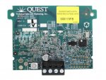
ScreenLogic2 Wireless Link Troublemaker

KDpoolguy

0
Bronze Supporter
Mar 5, 2017
603
Palm Desert, CA
Pool Size
17000
Surface
Plaster
Chlorine
Salt Water Generator
SWG Type
Hayward Aqua Rite (T-9)
Got my (used) ScreenLogic2 set up, but the wireless link clearly isn’t talking. The Protocol Adapter took the latest firmware update well and it can be found on the router with a dedicated IP address. I can see the protocol adapter on the app and Mac software, but it’s not picking up any info from the wireless link.

The problem is the wireless link. I have a rapidly flashing PWR light, but no Rx/Tx lights, I hung the indoor unit out a window within 10 feet of the outdoor unit and still no connection.

I checked the power to the outdoor unit with a multimeter (16.8V), but I wished there was a way to verify its operating. I do see these little buttons on both indoor and outdoor unit PC boards, not sure what they do???
Is the wireless link cooked?

If I have time tomorrow I’ll hook the Protocol Adapter up directly to the Easytouch board just to be sure it’s working.
 
KD,

I think it is a good idea to hard-wire a line to confirm that things are working...

I originally had my system hard-wired and then installed the wireless link. I connected each end and turned it on. It immediately worked... No fuss, no muss, so I am of no help here..

But Tom knows all about wireless links... Calling @ogdento

I do know that when running, both the inside and outside transceivers have solid green power lights and randomly flashing RX and TX lights.

Thanks,

Jim R.
 
hey Jim! KD and I have been chatting a bit already... his outdoor board doesn't do anything at all when powered up, no LED activity whatsoever. Mine flashes the right yellow LED once, and then the left green one rapidly (it's just a test board, i don't have it paired with anything)

There doesn't appear to be any reverse-input protection on the supply for these things, is it possible it got hooked up backwards? once would do it.
Do you see any signs of magic smoke having come out (burned traces, blackened components, that burnt electronics smell)?

The schematic for this board is online at the FCC website (under QTS0000LINK), and there's a load of test points on the board - but trying to determine if it's functioning by checking those points could be a long unsatisfying journey down a rabbit hole.

Tom
 
I did remove both PC boards and found the indoor unit has some sort of ‘leaked battery acid” look down the area of the power supply input. No visible problems on outdoor unit.
I wonder if I could swap the units-meaning use the inside unit for outside and vice verse? Aren’t they effectively the same thing?—meaning they’re just Tx-ing and Rx-ing the RS-485 info?
 
I only have an indoor board but I believe they are the same except I'm not sure if the power jack is populated on the "outdoor" board? I would not swap them before checking the input circuitry... just to be extra sure you don't blow up your protocol adapter. (I don't think swapping them is going to help you anyway)

This board does actually have reverse input protection on the supply... it's on the back of the board and I initially didn't notice it on the schematic ;)

To the left of the green comm connector is a white "reset" switch. Between that switch and the connector is a very small test point marked TP800... it is the power input AFTER the protection circuitry. Plug in your board and if you don't see roughly your supply voltage at the two red arrows in the attached photo, then something bad has happened to it. If you do see the supply voltage then you'll have to check the components farther down stream.

Here is a snip of the power input from the schematic (tp800 is circled in red):
quest tp800 schematic.PNG

Here is the actual board with red arrows showing where to measure DC volts:
quest tp800.jpg

Tom
 
Thanks Tom,
Gonna do this tonight. I’m gonna do the check on the indoor unit and outdoor unit. I took pictures of both before I buttoned them up and they are effectively the same, just the indoor unit had the DC power supply input soldered in. The date code is 2016, so it’s not too old—not like that makes much of a difference if it’s cooked.
 

Enjoying this content?

Support TFP with a donation.

Give Support
Just testing them now. Was out of the country for a few days, so just getting back to a regular circadian rhythm. Did the test on the indoor unit and the test points your mention have the same DC voltage (11.6V) and LEDs seem to work . Gonna tackle the outdoor unit now. It’s 110 degrees outside.
 
Here is a link to the images of front and back, and me testing the outdoor unit. Using the test points you mentioned, I’m getting a pass/good result. The DC power is the same at the power input points and the test (post protection) points.

The voltage usage is different from indoor and outdoor unit. Indoor has 11.6V and outdoor has 15.8V.

Let me know if you see anything concerning. The outdoor unit’s LEDs do not work at all. :(
 
Crud, i was hoping you'd get a fail on that test - which would point to a bad protection diode, capacitor or something stupid like that. just for kicks, do a voltage and continuity test on that reset switch and see if it's stuck... it's unlikely but there's no harm in checking. at this point i'd check to see if the microcontroller is getting a clock signal, and then if it's booting up and/or running... might take more time than it's worth.

strangely the only thing that looked bad was the smoke mark near the power input on the working unit!!
 
Strange, but these things cook outside huh? I do need to triple check the protocol adapter works. At this point I’ve found the 522620 on this site. Doesn’t it seem like a bumpin’ price?! That’s all I need, right?
I have a unused dog door about 15’ from the panel so I can wire the adapter directly with little difficulty. That was my original plan, though a wireless connection would be ideal.
 
I know, I saw it go up in $ today too. :(
Tested the Protocol Adapter and it works! Success! I too have the wired indoor controller and just took the cover off and connected the adapter to those wires.
 
Nice!! I didn't think to ask if you had an indoor controller... that is a smart use of it!

If you DO get a new wireless link set, I'm almost positive you can use it for BOTH the protocol adapter and the indoor controller - and have no wire at all going to your outdoor unit (they show that configuration in the intellitouch manual anyway).
 

Enjoying this content?

Support TFP with a donation.

Give Support
Thread Status
Hello , This thread has been inactive for over 60 days. New postings here are unlikely to be seen or responded to by other members. For better visibility, consider Starting A New Thread.