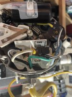
My question is if anyone knows what the resistance should be between L1 and L2 with the 115/230 jumper placed in the 115v position and the pump is disconnected from the AC circuit? Long story follows…
I’m adding a DEWENWILS WiFi timer to our Hayward 1.5 super pump set up on a 115v circuit. I’ve completed the installation and the timer is working correctly and in the process I replaced the outdoor box including a new Liquidtite AC whip harness to make the pool hardwired as the pump was installed using a regular plug. Our pool has been close for the season and the pump is in my workshop. I wired the pump end of the harness and being a retired copier technician, my AC motor knowledge is not strong (although DC and logic is) I decided to do a quick check of the wire installation for any possible pinched wires (very unlikely as it’s simply connecting three wires) by doing a resistance check between each wire to ground to see if any wires some how got pinched anywhere. This was done without the wiring being connected to any AC circuit. Overkill, but I’m a cautious guy.
No shorts to ground, but a short between the Black (L1) wire and the Red(“white”x115v, L2) wire within the new harness while connected to the pump. I then disconnected the harness from the pump and measured across the L1 and L2 connections on the pump and that was a short (no resistance). I suspect it has something to do with the 115\230v jumper position (which is in the proper 115v position) as the pump was working perfectly before being brought inside after the pool was closed. I found a good troubleshooting guide to check the winding resistance of the three sets in the motor and they all checked out correctly. I have no reason to suspect anything is wrong, it‘s just wasn’t what I was expecting. So I’m asking if anyone can confirm this on a Hayward 1.5 super pump.
Cheers!
Last edited:


