Relay modification/upgrade possibility?

DangerBoy

Well-known member
Oct 4, 2018
167
Calgary/Alberta
My '95 Hot Spring Grandee uses 6 of these 30A Potter & Brumfield T92S7D22-12 General Purpose DPST NO relays for controlling just about everything in the tub. Here's a picture of one.

P&B 30A Gen Purp Relay.jpg

They work great and last forever for running the circ pump, the jet pumps, etc. but running the heater is hard on them. The new heater that Watkins is using (a Hydroquip 6KW) has higher output than the original heater that tub came with and I find I'm having to replace one or both of the relays in the heater circuit (see wiring diagram below) at least once a year. I was paying about $30 CAD each for them plus a little shipping from Digikey but now I see I can get a Schneider Electric one from Mouser for about $17 CAD or ones that appear to be the same P&B relay from Chinese Vendors on eBay for ~$7 or $8 CAD (don't know if they're real or counterfeit though). In the final analysis, it's not really the cost that matters most to me; I just want to have more reliability and less downtime in the heating circuit and I think these relays are a little underdesigned for the loads this new heater puts on them and that's why they're not lasting near as long as they should. Methinks a modification/upgrade to that circuit is in order. 😈

I've been wondering if switching to a higher rated/more robust relay may be the solution to the problem. I've looked to see if anyone makes a 35A or 40A version of that same relay but it seems 30A is as big as anyone makes. I then wondered if I could maybe find solid state relays (SSRs) that could be substituted for the two electro-mechanical relays in the heater circuit but I couldn't find a DPST NO SSR anywhere. What I did find though were these SPST NO 40A SSR relays that you can get cheap on eBay.
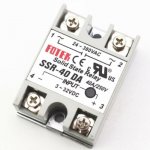
SSR-40A.jpg
I would have to use two of them for each of the two DPST relays that are in the heater circuit now (so 4 in total) so that will take some work but I think there's enough room in the control box to be able to do it. Do you think that could work/solve the reliability problem? What would be the pros and cons of replacing the original electro-mechanical relays with these SSRs? Below is the wiring schematic for the control box.
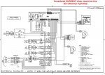
1995 Grandee electric.jpg
 
Your 6KW heater load is 27.3 Amps at 220V, so it's no surprise the 30A relays are failing. SSRs can be a good solution, but with your high load you need to consider the heat they generate from their internal loss. The data sheet I found on Ebay says 1.6V voltage drop, so at 27.3 amps that's 44 Watts for each relay or a total of 175 watts to dissipate. The SSR data sheet doesn't show its thermal path resistance to do a calculation, but you'll need a good size heatsink to keep them from overheating and failing.
 
@CA92807 and @dschlic1 Thanks for the advice. I was wondering about the heat issue with the SSRs as I've heard they can get hot. If I do the modification, I will order the 50 Amp SSRs instead of the 40s so they're running at a lower percentage of their capacity. I'll also stick some heat sinks on 'em to help them run cooler. Today I talked to a tech at Mouser about the problem and he also said he wasn't surprised the heater relays are failing. I asked him what he could suggest to replace those relays with and he found some big honkin' and expensive contactors which I can get used on eBay for an affordable price. The problem is they're too big to fit in the control box. 😖

I could certainly use your expertise on this thread that I just posted. Can somebody pls help me understand how this circuit works and figure out a workaround?
 
Last edited:
After some more looking around, I did come across some DPST NO non-latching SSR relays that I could use to replace those two constantly failing 30A P&B Gen. Purp. relays for the heater in my tub. They were very expensive though.

So then I thought that I could instead use two 100A SPST SSRs for each of those DPST relays. I figure those shouldn't get as hot as say a 40A or 50A SSR would handling such a low load. Or is the amount of heat SSRs generate independent of the rating of the relay vs the load they're handling?

The downside is that four relays instead of two are a bit more of a hassle to wire and they'll take up a fair bit more space in the control box. They're really cheap from China so having to buy 4 instead of 2 is no big deal.

But now I've just seen these 3 Phase SSR relays. I figure I can wire both 120V legs through two of the relay channels and not do anything with the third channel and I'd get the same thing as I would with a DPST relay which conducts both 120V legs through each side to give me 240 at the load. Then I'd be back to only 2 relays needed for the heater circuit instead of 4. Is that going to work like I think it will? I'm thinking of buying two 60A 3 phase SSRs instead of the four 100A single phase SSRs I was going to buy. What do you think would be the better way to go and why?

Edit: I have since found another vendor selling the 100A 3-Phase SSRs cheaper than this other vendor is selling 60A 3-Phase SSRs at. So now I'm looking at using two 100A 3-Phase SSRs in place of the two B&P 30A DPST Gen. Purp. relays. Good move? Will I still need to put heat sinks on the SSRs if I'm using 100A relays?
 
Last edited:
When an SSR switches on, there is a voltage drop across the TRIAC junction that’s mostly independent of the load, so a higher current rated SSR will only be slightly cooler due to its lower loss. The data sheet should show a value for "on voltage" at full load or at differing loads.

I don’t know why your controller has two relays in series as the flow sense, pump on and heat demand inputs could control just a single relay. Perhaps there is a safety code requirement for a fail-safe double air-gap switch when you mix 220 volts, water & people. That knowledge is outside my experience.

When an SSR is off there is still some small leakage current, perhaps a few mA at 220V, and that could be lethal.

With 4 SSRs replacing the old relays you have a massive amount of heat to dissipate. To get an idea, power up a 150W filament light bulb inside the controller’s enclosure and see how hot it gets.

You should measure the resistance of the heater element when off to determine the inrush current demand. Excessive demand could stress the SSR to the point of failure and failure could be open or shorted. SSRs are less forgiving than relays.

I applaud your initiative but I sense from your questions you haven’t worked that much with high-power controls. There are a lot of safety and reliability considerations to avoid a spectacular failure. Your 6KW load is equal to about 8HP. However, if things go bad, the 30 amp breaker will be happy to supply many times it rated value long enough to give you a really bad day. Easily 5x for a fraction of a second. That’s like having a 40 HP motor running wild is a small box, wanting to escape. This is seriously dangerous.
 
@CA92807, thank you for your post and advice. You re correct in assuming that I don't have a lot of experience dealing with high power controls.

I believe that the original control system had two relays in the heater circuit to engineer more safety into the system. On the control circuit for the main heater relay there is the flow switch so that gives you the no heat if no flow safety you need to protect the heater. The load current going into that relay is supplied from the heater interlock relay which is on a different control circuit. I believe that circuit was controlled by the system's logic and was used to stop load current from going to the heater relay if the high temp limit was detected by the high limit thermistor at the outlet of the heater. That way, if the temp sensor thermistor goes bad and the system continues to heat the water up to the cutoff limit, the heater interlock relay will be opened and load current will cease going to the heater relay.

The heater my control system was originally designed around was 5.5 KW but the new ones Watkins is going with are 6KW. The voltage here is 120 so the heater is running off of 240. At 5.5 KW the heater load was then about 23A and at 6KW it's 25A. I'm guessing that with the heater relay only being rated for 30A, that doesn't leave a lot of headroom for inrush current. At any rate, I think the 30A relays the system was designed around are taxed too much by this higher output heater and this is why one or both of the heater relays fail so frequently. Sometimes these relays can fail closed (I have seen it) leading to an overheat situation which is potentially dangerous. Given that, I think it's apparent that I need to replace those relays with something that can handle the extra loads more easily.

I've looked at higher capacity contactors to replace them with but every one I've looked at is way too big to fit in the control box. They're also prohibitively expensive unless you buy used. After doing all of the research I've done, the only possible viable alternative I can see is to replace those two relays with high capacity SSRs as they are within my budget and will fit in the control box. Do you have any other suggestions?

With that in mind, let's look at the problems we might encounter with a switch to SSRs and how we might mitigate them. You said that there can be a small leakage current in SSRs. According to the specs on the 100A SSR I'm looking at buying leakage current is rated at ≤3mA and the turn off voltage is <1.5V. Other vendors I've seen selling what I think are the same relays with a different label on them say the leakage current ≤8mA. Is this amount of leakage going to be an issue for me? Are there any countermeasures I could use to mitigate the problem like using a bleeder resistor ?

The resistance through the heater element is about 10.8 ohms when the tub water is at normal temperature and the heater has been off for a long time. I don't know how to calculate the inrush current demand so maybe you could help me out with that. But if the normal load is 25A and I use 100A SSRs, is inrush current demand going to be that big of an issue for me? It seems to me inrush current demand would be a bigger issue to me with the 30A relays I'm currently using than they would be with 100A relays.

Then there's also the heat issue. Instead of four SPST NO 100A SSRs, I plan to use two 3-Phase 100A SSRs which are basically TPST relays. I just won't use one of the legs to make it them DPST. Voltage drop on those SSRs is ≤ 1.3V so at 25A that's 32.5W each or 65W in total to dissipate. I can definitely put heat sinks on each SSR so that will help dissipate a lot of the heat. The original Watkins control box is steel and the other Watkins IQ2000 control box I could use is plastic but has a large flat long and narrow (like 18" x 3") aluminum plate going all the way across back of it. I suspect that one of that plate's functions may be to act as a heat sink for some of the components in the IQ2000 system that are anchored to it but it may also be there for other reasons such as grounding and mounting. If I use the IQ2000 box and can make sure the SSRs' heat sinks are thermally connected to that plate, that should help conduct some more of the excess heat away from the SSRs. If I use the original control box, the SSR heat sinks will be in direct thermal contact with the black steel control box which has a lot of surface area so that should help dissipate the excess heat as well. Hopefully, that adequately addresses the heat issue.

Are there any other things I could do to make the system more safe to use SSRs in place of the constantly failing mechanical relays?
 
Sorry I didn't see this thread sooner. SSR's would be better in that your heater is being hot switched, and that is what is probably burning up the relays. You could try using a bigger physical relay or also use a SSR. In general one of the primary uses for SSR's is to switch heating elements on and off for this very reason.

The SSR isn't without issue though.. they actually usually fail shorted. So there is an obvious issue here without adding some sort of thermal fuse or safety feature in line. They do also exist you can get them from a reliable source like Digi-Key, Mouser, etc. You want to figure out how to add a safety feature if you switch to SSR's. It might sound crazy, but you could use one of these devices to detect a SSR failure by switching a mechanical relay off to the heater. If it overheats, it melts and shuts the circuit down. You could probably also use something like an Arduino to detect if the heater is stuck on as well (like if the SSR is on for a long time), and have it shut off a mechanical relay. As long as you are not cycling that relay it should not wear out on you. It could even be a NC contact...

I wouldn't do it otherwise because, will the heater just burn out if it's stuck on? If it does, would it be less expensive to protect it? Probably.

All the comments on the triacs and internal resistance of SSR's are true, so I won't repeat them.. so you do need to deal with that as well. You need the physical room for the heatsinks and an absolute minimum are the DIN rail ones you see sold everywhere. Honestly, in your application they probably are not big enough.

One last comment that is also a safety comment. There are a lot of very inexpensive Chinese SSR's on the market now. Many of them are fake copies of questionable designs to begin with. I use them in a lot of things, actually, and most are okay, some fail. The things I use them in have me there in person with it most of the time. If I were going to use one in your application, then I would strongly consider buying name brand ones from an electronics distributor instead of Amazon or eBay. I'd tell you that a real Fotek is probable okay, but if you can figure out for sure that is what you got, you are smarter than I am.

Don't worry about the leakage current for your application. You won't even be able to notice it.
 
@Rattus Suffocatus Thanks for your input. When you're talking about overheat protection system, are you talking about a system to detect overheat in the SSRs or the hot tub water in case the SSR fails shorted?

The system I have has 2 levels of overheat protection for the hot tub water. The load current going to the heater relay comes from the output side of the heater interlock relay. That relay is tied into the high limit temp sensor so even if the heater relay fails shorted, the system will detect it and shut signal current off to the heater intelock relay thereby depriving the heater relay from load current. This shut down requires a power-off restart to start the system back up again.

Now if both of those relays fail shorted then the second line of defense is the thermal cutoff switch in the heater itself. Failing shorted can happen just as easily with the mechanical relays the system is using as well and may even be more likely to occur with them than with SSRs if I use (real/not counterfeit) 100A SSRs to handle 25A + inrush current rather than 30A mechanical relays to handle 25A + inrush current.

When I got my tub second hand I knew there were problems with it but I didn't know one of them was that the heater relay had failed shorted. Another one I didn't know about was that the high limit temp sensor thermistor had drifted so the water temp got up a lot higher than the designed 116F cutoff limit (I think it hit 130F) before the high limit system kicked in and shut down the tub. Luckily, nothing was damaged. That started me on the journey to getting to know everything I could about how this hot tub works. I've learned a lot since then. Had I known then what I know now, I would've caught both of those problems and fixed them before starting the tub up for the first time.
 
OK. Well I don't have a schematic in front of me. Yes I meant a pool overheat. You can compensate for the SSR's heat with adequate heat sinking and or fans.

Yes regular relays, especially with a hot switch arc can weld on too. 130F is dangerous for you but not the materials in the tub necessarily.

If you indeed have multiple overheat protections already go ahead and experiment. The issue with bad counterfeit (and good counterfeit) relays is real, look it up.

The triacs in SSR's usually fail shorted on, so I wanted you to know that before you proceeded because this is more than my smoker or my brew kettle if things go bad.

I think you are on the right track. I just wanted to make sure the safety features were there, and you knew about the unfortunate situation with SSR's in 2020.
 

Enjoying this content?

Support TFP with a donation.

Give Support
People who have already commented seem to know far more than I about these SRRs. I purchased a 60 amp version of what you posted to control my 6 Kw sauna heater. It is constructed on a thick aluminum part that will become a heat sink if is attached to anything metal. You could just use screws to attach it to the inside of the wiring box if it metal.
 
Last edited:
@Rattus Suffocatus The schematic for my hot tub's original control system was included with my initial post on this thread. Scroll up to the top and you'll find it if you're curious to look at it.

Thank you for making me aware of the counterfeit relay problem. I did read up on it and started to look at how I can be sure to get genuine Fotek TSRs as I know there are lots of counterfeits out there. To begin with, I went to the Fotek website and found out that the largest DA TSR they make is 75A so now I can tell when a vendor is selling counterfeits when I see them selling 80A or 100A Fotek TSRs. I also found out that the dimensions of their TSRs are slightly different than the cheap TSRs the counterfeit Foteks are based on. So another way to help tell you're getting the real thing is to only buy from a vendor who publishes the size specs of the TSRs they're selling and make sure the specs match those of Fotek's and not the knock-offs/cheap brands.

I also got in contact with Fotek and asked them to help me to acquire genuine relays and they responded very quickly and are helping me now. With their help I feel pretty confident I can be sure I'm acquiring genuine relays when I make my purchase.
 
Okay.. good luck.. there are some decent clones out there (Inkbird is likely one of them, but they don't sell it as a Fotek) but what you are doing isn't something to screw around with. I think you'll be fine with real SSR's and adequate heat sinking since there are other thermal protections on the tub. Spend the money for the real units, and overdo the heatsinks and you should be fine. It's better to control a large resistive load like a heater with a SSR anyway. The reason, with water present, they are using DPDT relays by the way is to isolate both Hots from the heater.. not a bad idea with water present. Though in theory your GFCI panel should pop if one broke loose anyway. Usually that isn't done even at 220V with heaters. How often does the interlock relay cycle? Maybe you can leave that one mechanical. If it's only "once in awhile" leaving it mechanical will be much more simple for you.

I didn't see the schematic on my phone for some reason but it's there on a computer.
 
The Interlock relay cycles very infrequently but I still seem to burn them up fairly often. The last one I replaced had failed shorted. That's not good since it's the relay that's supposed to cut power to the heater in an overheat situation so I think I'll be better off if I replace heater relays with TSRs. I just need to get a pair of ones I know to be genuine ordered and on their way to me. Hopefully, Fotek will be able to help me with that.
 
I'm just seeing this thread. I have a Jacuzzi J-375, which has a Sundance controller. They use dual relays to switch a 5.5kw heater ... They use a "Potter and Brumfield" which now seems to be called TE connectivity T92S7D12-12, which is rated to 40A. They use 2 for the power circuit to the heater. I assume they use 2 in case one fails in the ON position. I know this information may be a little late for you, but figured you may like to know anyway.

Bruce
 
@bwilford The relays you speak of are the same as what my system uses. The 40A rating is like a peak rating and for sustained use their rating is 30A. The system in my tub was originally designed with a 5.5 KW heater just like yours. Watkins later made that heater obsolete and stopped selling it and then made their standard heater a 6 KW for bigger tubs. They also offer a 4 KW version of the same heater for smaller tubs. I suspect these relays worked okay with the original 5.5 KW heater but they were probably just enough for those heaters. It appears the 6KW heater pushes them a little too hard so they tend to fail a lot earlier - at least that's been my experience.

I think your suspicions about the purpose of the second relay is correct. My guess is your system uses 2 relays in the heater system the same way mine does. One of the relays is the heater relay that supplies load power to the heater. The control signal to that relay is governed by a system that works with the temperature sensor; when the temp sensor tells the system the temperature is below the set-point, the system calls for heat and sends the control signal to the heater relay which causes the heater relay to latch and load power goes to the heater. When the temp sensor senses that temperature exceeds the set-point, the system turns off the signal power to the heater relay causing the relay to unlatch so no more load power goes to the heater.

The other relay acts as a heater interlock relay; it provides the load power to the heater relay but it is not controlled by the same circuitry. It is controlled by circuitry that uses the high-limit sensor for input. So what happens is the high limit circuit is programmed to supply control signal power to the heater interlock relay as long as the temperature is below whatever the high-limit set-point is. On my tub that's around 116F or so but I can't remember exactly what it is. So as long as the water temp is below the high limit temp, the heater interlock relay is getting signal to keep it latched and sending load voltage over to the heater relay. This enables the heater circuit to send load power to the heater as needed.

Now let's say something happens like the temperature sensor fails in such a way that the heater control logic thinks the water is a lot cooler than it actually is or the heater relay fails shorted which means it stays latched no matter whether the system is calling for heat or not (I've had those P&B/TE Connectivity relays fail that way so it can happen). In either of those cases, the heater will keep heating the water well beyond what the set-point is set at (e.g. 104F) and in the case where the heater relay has failed latched, there will be nothing to stop the heater from continuing to heat the water. This is where the heater interlock relay comes into play. Once the water temperature reaches the programmed high limit temperature as sensed by the high limit sensor, the heater interlock relay will unlatch and stop sending load power to the heater relay and the heater will be shut off. At that point also, the logic of the system will likely shut down just about everything and will require a manual restart in order to restart the system. If it didn't do this, the heater interlock circuit may continue to maintain the system at the high-limit temperature turning the system off at the high limit and turning it back on at some point just below the high limit.
 
Last edited:
@DangerBoy You could be correct about the heater interlock relay. The Jacuzzi circuit diagram shows two temperature sensors, one labeled "temperature sensor", the other labeled "Hi-limit / Freeze sensor". Just FYI, I did just finish up an app for my iPhone that uses Blynk, that allows me to see and adjust the hot tub temp from the phone, see the pH from my phone and also control the chlorine pump from my phone. All over wifi.
 
@bwilford I also have a wifi enabled system that I'm putting in that will allow me to inject chlorine with a dose pump using my phone but it's just a "dumb" system that doesn't allow me to see what the FC level is. I just know that every time I cycle the dose pump it injects enough chlorine to raise the FC level by 2 ppm. I can also turn on the jet pumps for three minutes or however long I program them to be on with my phone. At present, I cannot see or adjust the temp with my system but I would like to have that ability. I would like to learn how you did that with your system. Okay if I PM you?

The system I have is just a first step; I wanted to prove the concept and gain the capability of injecting chlorine and circulating it remotely and doing it inexpensively which I have done. That was all within my present capabilities. The next stage - if I want to take it that far - would be to use a Raspberry Pi or something similar to monitor FC levels in the tub (maybe with an ORP probe?) and have it control the Chlorine dose pump to create a self-regulating Cl injection system. Getting to that stage is out of my wheelhouse at present and will require me to expand my knowledge and technical capabilities somewhat. I think it's all quite doable if I'm willing and able to put in the time and work to learn what I need to learn.
 
Yes, it's OK to PM me, can you do it through TFP ? I think it's possible. I use the raspberry-pi to monitor temp from the hot tub, I also added a pH probe. Atlas scientific are or were working on a chlorine probe. But I do exactly what you do I use a peristaltic pump to add 2 ppm of chlorine every day.
 

Enjoying this content?

Support TFP with a donation.

Give Support
Thread Status
Hello , This thread has been inactive for over 60 days. New postings here are unlikely to be seen or responded to by other members. For better visibility, consider Starting A New Thread.