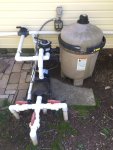
Pump motor and GFCI receptacle wiring question

May 30, 2018
64
Northern NJ
I'm in the process of replacing my pump motor, and am rewiring/replacing the rusted out junction boxes, conduit and corroded switch and receptacles near my pump. The previous owner/pool installer has a 20A breaker in the sub panel than runs to an Intermatic T104 timer. The timer then goes outside the shed to a switch (manual switch) and then to a GFCI receptacle, then a standard receptacle, and then to the pump motor.

Assuming my current motor is running @ 230v (based on seeing the T104, but I will test with multimeter as well), is it ok to run the 230v through the switch, GFCI and regular outlet (existed GFCI receptacle is 125v) to the 230v motor? Just trying to understand if the higher voltage passing through from timer to motor needs to pass through switches/receptacles all rated at 230v as well.

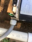
Additionally, the wiring used is like Frankenstein's monster. Looks like an air conditioner whip (flexible conduit with wiring pre-installed) was used to connect the motor to the receptacle. On the surface it looks fine, but it must be 10 or 8ga stranded wire in that whip, while the receptacles appear to be connected with 12ga solid, then 10 or 12ga stranded wire connects the GFCI to the switch, and the switch appears to have 12ga solid going back to the timer. In short, a mess and next to impossible to connect everything cleanly and fit it in the junction box. Given that I have a 20A two-pole breaker in my subpanel that feeds all of this, is it safe to say that 12ga solid wire from timer to pump motor will suffice? Motor is 1hp and about 5 feet from the panel.

Thanks in advance. Appreciate any confirmation or insight anyone can provide.
 
If you want to bring the wiring up to code the pump should be on a dedicated GFCI CB. The outlets should be on its own CB.

What type of pool is this?
 
Yikes. In short, anything fed from a 2-pole breaker must be rated for 220vac. A picture might help a lot in figuring this out.

Let’s see if this works - I’ll try posting photos showing the setup from house > shed > pump

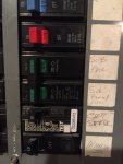
Breaker in house on main panel. Appears to be 30A two pole going to shed subpanel.
235654FA-1F4B-47E0-A2C5-040E017773A7.jpeg

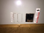
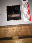
Subpanel in shed. One 20A two pole breaker. The shed current has a single light bulb and outlet inside, and outside has the pum
E2270DBA-C8A3-45A8-AD75-62C9B042A47B.jpeg0D35CCDC-8B80-4D89-ABB9-8AE8D6183895.jpeg


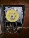
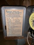
Timer in shed, after the panel/breaker
51792A57-116B-4F89-BF42-3BCC46CF3C5D.jpeg30000121-168F-4DCB-84FE-12D23BD7C8ED.jpeg


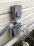
Switch, GFCI and regular outlet outside shed, after timer and before pump
E10313BB-367C-4515-A823-33B5C7A6F214.jpeg

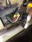
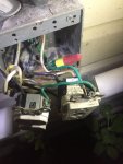
Guts of junction box housing the receptacles
0A35AD25-CAC2-4080-AE7A-2C30D3E43431.jpegD4D3D778-1A41-4626-B283-852AECE3D74A.jpeg

Whip from junction box to pump
E4611474-112B-4608-933F-ABB47D675EA1.jpeg0984B07F-1AE1-45E1-AA0C-20B7B610B1BE.jpeg


Any thoughts? Can I remove the receptacles entirely and just wire the switch to the pump for now, and have it fixed proper in 2 weeks when the electrician comes out? In theory wouldn’t that just be 230v all the way (breaker, timer, pump)?

Would the “correct” setup here be a 230v GFCI breaker for the pump only, rather than a non GFCI breaker and the 125v GFCI receptacle in-line? Then have a second breaker in the subpanel for my shed light and outlets?

Thanks. Main goal now is to safely get the pump going again, even if it’s just a temporary solution.
 
It looks to me like you are 120V all the way and have a 120V motor.

I can see black, white, and green wires going into the motor.

The timer label says it is a DPST timer but the mechanism is a 120V SPST timer.

240V is two hot wires and a ground. Typically two black wires and a green ground wire. 120V is one hot wire, neutral, and ground. Typically black, white and green.

The 120V pump runs though the GFCI outlet for protection.

It looks like the wiring from the subpanel was made 120V at some point in time.
 
Last edited:
It looks to me like you are 120V all the way and have a 120V motor.

I can see black, white, and green wires going into the motor.

The timer label says it is a DPST timer but the mechanism is a 120V SPST timer.

Interesting. So what’s the best next step? Multimeter to confirm voltage coming out of subpanel breaker? Nothing in this house seems to have been done correctly so I don’t want to rely on the wire colors used.

Assuming it is all 120v from panel to pump, is the original sequence of wiring ok? That would be:

Subpanel > Timer > outside switch > GFCI Receptacle > standard receptacle > pump
 
Will it work, yes. Is it to current code, no. Is it safe, probably. As long as you don’t plug too much amperage into the outlets. You can easily overload that circuit.

Current code requires a dedicated GFCI circuit for the pump and a separate CB for the outlets.

You have to open up the subpanel and show the way the wire that runs to the timer is connected. Measuring the voltage at a CB does not tell you how circuits are wired. And you should not be sticking probes into a live CB panel. If you understand the way a CB panel works then you can determine it visually.
 
I'm no licensed electrician; however, I have 30+ years' experience working for electric utilities, mostly in engineering.

I am not giving advice!!

If it were my installation, I'd certainly feed the pump off of a 2-pole GFCI breaker with no other elements in the circuit; if there were a subpanel in my shed, I'd have it there with a regular breaker in the main panel feeding the subpanel. I'd also check to make sure whether AFCI is needed for any other circuits in the main or subpanel - since I'd be rewiring, I'd want/have to make sure all the updated code requirements are met!

If I were to put in a timer switch, I'd use a 2-pole switch to open both hot lines. I'd determine the max load for my pump, then size the wire and the GFCI breaker for that, making sure the wire size matched or exceeded the breaker's continuous rating -- no smaller than 12 AWG for 20-amp or 14 AWG for 15-amp, for example.

It might cost a touch more to do it that way, but not nearly as much as the liability if someone got hurt or the insurance nightmares if I had a house fire with all the code violations of doing it otherwise! One of the counties served by my utility has no electrical inspectors; we always advise of the risk of unlicensed work and code violations and the possibility that insurance policies may be violated and the homeowner left to suffer the loss, even if the fire was not caused directly by the incorrect wiring.

And the "A/C whip" you refer to is "liquid-tight" flexible conduit. Nothing wrong with that unless local codes prohibit it.
 

Enjoying this content?

Support TFP with a donation.

Give Support
Will it work, yes. Is it to current code, no. Is it safe, probably. As long as you don’t plug too much amperage into the outlets. You can easily overload that circuit.

Current code requires a dedicated GFCI circuit for the pump and a separate CB for the outlets.

You have to open up the subpanel and show the way the wire that runs to the timer is connected. Measuring the voltage at a CB does not tell you how circuits are wired. And you should not be sticking probes into a live CB panel. If you understand the way a CB panel works then you can determine it visually.

Thanks. Will open the panel and snap some pics and post this evening.
 
Check the voltage at the black and white wires at the pump motor. That tells you what you need to know.
 
I'm no licensed electrician; however, I have 30+ years' experience working for electric utilities, mostly in engineering.

I am not giving advice!!

If it were my installation, I'd certainly feed the pump off of a 2-pole GFCI breaker with no other elements in the circuit; if there were a subpanel in my shed, I'd have it there with a regular breaker in the main panel feeding the subpanel. I'd also check to make sure whether AFCI is needed for any other circuits in the main or subpanel - since I'd be rewiring, I'd want/have to make sure all the updated code requirements are met!

If I were to put in a timer switch, I'd use a 2-pole switch to open both hot lines. I'd determine the max load for my pump, then size the wire and the GFCI breaker for that, making sure the wire size matched or exceeded the breaker's continuous rating -- no smaller than 12 AWG for 20-amp or 14 AWG for 15-amp, for example.

It might cost a touch more to do it that way, but not nearly as much as the liability if someone got hurt or the insurance nightmares if I had a house fire with all the code violations of doing it otherwise! One of the counties served by my utility has no electrical inspectors; we always advise of the risk of unlicensed work and code violations and the possibility that insurance policies may be violated and the homeowner left to suffer the loss, even if the fire was not caused directly by the incorrect wiring.

And the "A/C whip" you refer to is "liquid-tight" flexible conduit. Nothing wrong with that unless local codes prohibit it.

Thanks for this - sounds like what i'd like to get done.

At the house in the main panel there's a 2-pole 30A breaker out to the shed. I assume this is the only thing feeding power out there. From what I can tell this 30A breaker is neither GFCI or AFCI. I'm still confused as to if this is a 115 or 230 setup, why i see 115v referenced in some places, 120v elsewhere, 220, 240 etc. Need to find a good source of info to read up and better understand how all of this works and how to identify. I've done a good share of outlets, fixtures, switches, etc. but this is a step more involved for me. I'm sure I can get there, but definitely want to read and better understand it all, even if I end up hiring the electrician to do it all anyway.

Regarding the timer - is the one I have pictured 2-pole? I'm struggling to determine what I have now given the previous poster saying the label didn't match the timer. Can you explain why you say you'd use a 2-pole to open both lines? Mainly interested as to why it's optional (as you seem to imply) and what the 2-pole operation would provide vs a single pole

Lastly, the "whip" (as the Lowes website called it) seems fine to me. I was really only questioning the wire inside of it. Much thicker than anything else in the junction box and stranded. Nearly every connection seems to use a different type/gauge of wire. Very strange and a nightmare when trying to make connections, as the pump wires in that flexible conduit wouldn't fit on the receptacle screws, thus forcing wire nuts and pigtails to get things connected, crowding the already tight box.

Appreciate you insights on this.

As for the breaker and wire sizing coming from the subpanel -- the motor i'm planning on putting in (1hp single speed) is likely a temporary solution as we're planning to convert to salt in a year or two and I'll likely overhaul the entire pump and plumbing situation then. If moving from a single to a dual or VSP, would I expect the max load to decrease in those cases? No plans on going to a bigger pool or adding things like water features. Heater maybe, but not sure.
 
Can you read the plate on the motor? It should say 120v or 220v. The wiring makes it look like 120v.

Label on existing (to be replaced) motor says 230/115, so not much help. There should be a switch though, correct? The new replacement motor has a dial where the voltage needs to be set, depending on the wiring configuration.

Pardon my skepticism, but would it be possible that the motor was set to 115 despite the wiring feeding in 230 (or vice versatility)? Would the motor be functioning for X years under those conditions? I am beside myself with the type of problems I’ve been encountering in my house lately and nothing seems beyond the realm of possibility anymore....
 
That wiring and motor is 120V. I am confident of that.

Motor voltage is changed with the wiring. Most dual voltage motors don’t have a switch for that.
 
Thanks for this - sounds like what i'd like to get done.

At the house in the main panel there's a 2-pole 30A breaker out to the shed. I assume this is the only thing feeding power out there. From what I can tell this 30A breaker is neither GFCI or AFCI. I'm still confused as to if this is a 115 or 230 setup, why i see 115v referenced in some places, 120v elsewhere, 220, 240 etc. Need to find a good source of info to read up and better understand how all of this works and how to identify. I've done a good share of outlets, fixtures, switches, etc. but this is a step more involved for me. I'm sure I can get there, but definitely want to read and better understand it all, even if I end up hiring the electrician to do it all anyway.

Regarding the timer - is the one I have pictured 2-pole? I'm struggling to determine what I have now given the previous poster saying the label didn't match the timer. Can you explain why you say you'd use a 2-pole to open both lines? Mainly interested as to why it's optional (as you seem to imply) and what the 2-pole operation would provide vs a single pole

Lastly, the "whip" (as the Lowes website called it) seems fine to me. I was really only questioning the wire inside of it. Much thicker than anything else in the junction box and stranded. Nearly every connection seems to use a different type/gauge of wire. Very strange and a nightmare when trying to make connections, as the pump wires in that flexible conduit wouldn't fit on the receptacle screws, thus forcing wire nuts and pigtails to get things connected, crowding the already tight box.

Appreciate you insights on this.

As for the breaker and wire sizing coming from the subpanel -- the motor i'm planning on putting in (1hp single speed) is likely a temporary solution as we're planning to convert to salt in a year or two and I'll likely overhaul the entire pump and plumbing situation then. If moving from a single to a dual or VSP, would I expect the max load to decrease in those cases? No plans on going to a bigger pool or adding things like water features. Heater maybe, but not sure.

As for voltage, US standards (if a reader is not in the US, s/he will not find this useful) require a utility to maintain a +/-5% tolerance at the point of service, typically the meter. The nominal voltage is 240 supplied with a center tap, so there are three wires into the residence; one is a grounded neutral and the other two are “hot”. Connecting across either hot and the neutral gives 120V, while connecting across the two hot legs gives 240V. The tolerance means the voltage at the meter should always be (except in abnormal/emergency conditions) between 228 and 252 or 114 to 126, depending on what’s connected.

However, by the time a device is connected at the outlet or panel, the voltage drops slightly because of the resistance in the wiring. Therefore, most devices in the US are designed to operate at 110 or 220V. Manufacturing standards allow for +/-10% variation before the device is at risk of failure, so that 99-121 or 198-242 shouldn’t be a problem.

So, 110, 115, 120 really are all the same, as are 220, 230, 240.

In a service panel, a breaker that takes one space is the 110/115/120 class, and a breaker that takes 2 spaces is 220/230/240.

Note that a separate “ground” wire that is bare or has green covering will/should be run from the main service panel to EVERYTHING, and no ground rods other than the one connected in the MAIN panel should be anywhere. The ground wire is not designed to carry current, but the neutral (usually white in the US) is expected to carry load current.

AFCI breakers sense sparking wires that don’t generate enough current to trip the breaker for overload or ground-fault levels, the original functionality of breakers and GFCI, respectively. They’re now required generally in “living spaces”. GFCI sense small imbalance between the current being sent out to the load and the current coming back — a giveaway that there’s a “leak”. They’re used in places where chances are higher that a person could be part of the path in that “leak”. It takes way less current to injure/kill than it does to overload a breaker, so the GFCI sensitivity is way higher than the overload rating (it will still open on its overload setting, too, though).

Technically, then, AFCI’s detect waveform anomalies regardless of current levels, GFCI’s detect small levels of current imbalance, and all sense high current levels that could overheat the downstream wiring.

Regarding the timer, The label photo shows it is “2-pole, single throw”, meaning there are two switches that operate the same way at the same time. For your 220/230/240 loads, you’d use one switch for each of the two “hot” wires (likely both black or one red and one black). The reason is so that when the switch opens, there is no voltage on either wire leaving the switch. You could open only one wire and the motor would stop; however, there’d still be voltage feeding into it from the “other” wire. Operationally ok, just not safe.

Finally, stranded wires are generally thicker-seeming than solid for the same ampacities. The AWG rating is the key - never use smaller wire than the breaker is rated for; it will overheat before the breaker trips.

[SOAPBOX ON]
PLEASE NEVER EVER TAKE THE “IT’S TOO INCONVENIENT TO BE SAFE” approach (not targeted to you, per se -seems like you’re after doing it right). I’ve been to a friend/coworker’s funeral. That’s WAY less convenient, WAY more costly. And it’s traumatic for WAY TOO MANY people.
[/SOAPBOX]
 
Thread Status
Hello , This thread has been inactive for over 60 days. New postings here are unlikely to be seen or responded to by other members. For better visibility, consider Starting A New Thread.