Proposed install for Aquarite

peril

0
LifeTime Supporter
May 20, 2012
63
Allen, TX
Pool Size
12000
Surface
Plaster
Chlorine
Salt Water Generator
SWG Type
Hayward Aqua Rite (T-9)
Hi All,

I've done my research (YouTube, google and tfp) and found lots more support on fixing aquarite vs aquapure, so planning on going with a 25k aquarite for my 12k pool. Have a couple of photos to share and wanted to get some ideas on the best way to retro fit it.

  1. 02 shows the proposed install of the flow controller (last thing before the Jandy valve to the waterfall and skimmers returns), and the swg cell.
  2. 01 shows the existing plumbing - I was going to try and heat up the existing PVC in the Jandy valves (return / spa), and pull it out and install the flow controller on a set of unions
  3. 04 shows where I intend to install the swg - that is pretty straighforward (aside from being on a 10-20 degree angle)
Questions
  1. For 01 - I'm planning on cutting out and then heatgunning out the little bit of PVC - anyone see any problems with this, I could do the chisel method too - but I like the cleanness of the PVC heat gun
  2. For 03 - the run for the SWG is on a 10 to 20 degree incline - I don't see any problems with this as the gases should end up in the return line - I could make this vertical or horizontal but will end up adding 90s, which is not a love of mine
I'm not against the aquapure per say - but the oem cells and support for the aquarite look good; and haven't read a lot of problems with either system (side from the Truclear not being quality here - which is good enough for me to make a purchasing decision.)

-Adrian
 

Attachments

  • 01 overview.jpg
    01 overview.jpg
    757.8 KB · Views: 13
  • 02 sensor location.jpg
    02 sensor location.jpg
    752.5 KB · Views: 13
  • 03 swg location.jpg
    03 swg location.jpg
    795.7 KB · Views: 9
  • 04 swg vertical.jpg
    04 swg vertical.jpg
    772.6 KB · Views: 13
Last edited:
You should not install the flow switch on one side of the valve and the cell on another leg past the valve. That is a way for the flow switch to keep the cell powered when there is no water flow.

Note that the Aquarite has a history of burning up components ion the board. People say that with the addition of the K3 relay and V1.59 firmware the problems are fixed but the jury is still out on that. If you don't have Hayward automation or VS pumps there are other choices that don;t have a history of components overheating.

 
  • Like
Reactions: peril
You should not install the flow switch on one side of the valve and the cell on another leg past the valve. That is a way for the flow switch to keep the cell powered when there is no water flow.

Note that the Aquarite has a history of burning up components ion the board. People say that with the addition of the K3 relay and V1.59 firmware the problems are fixed but the jury is still out on that. If you don't have Hayward automation or VS pumps there are other choices that don;t have a history of components overheating.

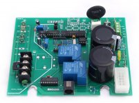
We always had issues with the little round part at the top right of the picture. Very premature failure
 

Attachments

  • opt-pcb-rite_1000x.jpg
    opt-pcb-rite_1000x.jpg
    95.3 KB · Views: 2
  • Like
Reactions: peril
We always had issues with the little round part at the top right of the picture. Very premature failure

That round part is the thermistor on the main board. The good news is it is replaceable as described in the link in post #2.
 
  • Like
Reactions: peril
You should not install the flow switch on one side of the valve and the cell on another leg past the valve. That is a way for the flow switch to keep the cell powered when there is no water flow.

Note that the Aquarite has a history of burning up components ion the board. People say that with the addition of the K3 relay and V1.59 firmware the problems are fixed but the jury is still out on that. If you don't have Hayward automation or VS pumps there are other choices that don;t have a history of components overheating.

+++ and ACK - The install will be opposite cell will be before the Jandy valve; intent is to only have the chlorinator running when there is pool flow - otw - valve will be in the spa mode, and won't be able to generate. In reviewing the install docs - it's install (2) below - even tho the my pics are bad. The one you describe is scenario (4) which is no good - as the chlorinator could be running when the flow is to the spa.

[snip]
Code:
pump -> filter -> heater ->  03 ***swg ****-> Jandy valve -> pool -> 02 flow switch -> return jets + spa overflow
(this all exists to align the Jandy valve spacing with pool)-> spa


1630972941033.png
 
Last edited:
  • Like
Reactions: Diggy77
This is where I ended up - +++ and thanks a lot to @Diggy77 @ajw22 for reviewing.

One trick I learned was the reuse the fitting heat gun trick, cut the PVC pipe off to 1/2 -1" from flush to the jandy valves, and then heated up the remaining PVC in the ABS with a heat gun for 45ish seconds, and then peeled it out with needle node pliers. Make sure to dry out the Jandy valve before you put the heat on - I mangled one pretty good.

That was a LIFESAVER -and made the plumbing side of the job one heck of a lot less stressful.

--Adrian
 

Attachments

  • IMG_1100.jpg
    IMG_1100.jpg
    993 KB · Views: 6
  • IMG_1101.jpg
    IMG_1101.jpg
    849.6 KB · Views: 7
  • IMG_1102.jpg
    IMG_1102.jpg
    833.6 KB · Views: 6
  • IMG_1103.jpg
    IMG_1103.jpg
    830.2 KB · Views: 7
  • IMG_1104.jpg
    IMG_1104.jpg
    874 KB · Views: 7
Thread Status
Hello , This thread has been inactive for over 60 days. New postings here are unlikely to be seen or responded to by other members. For better visibility, consider Starting A New Thread.