Pool equipment relocation/replumbing suggestions.

ShinDiors

Well-known member
Jul 16, 2021
227
Northern VA
Pool Size
20500
Surface
Plaster
Chlorine
Liquid Chlorine
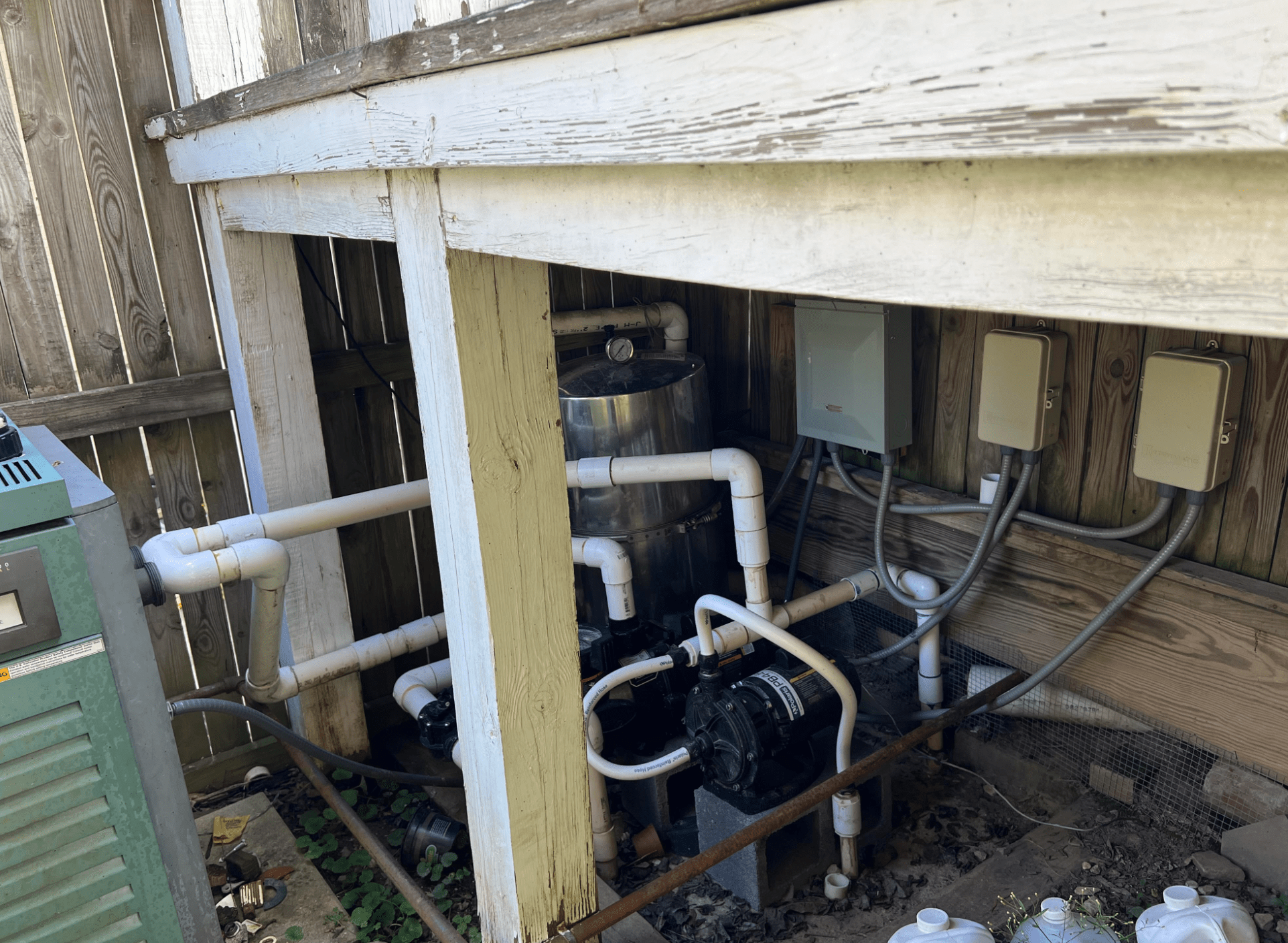
We are converting the ground level deck into a paver patio and during the process we decided to tear down this pool equipment shed and removed the gas line that were underneath the deck (pool heater was dead and we may consider that later with above ground gas line). So now we have about an extra foot behind the DE filter and no height restriction, I would like to get some suggestions from you guys about replumbing and better location of the equipment overall. Hopefully I could use my general contractor to do this before the pool opening.

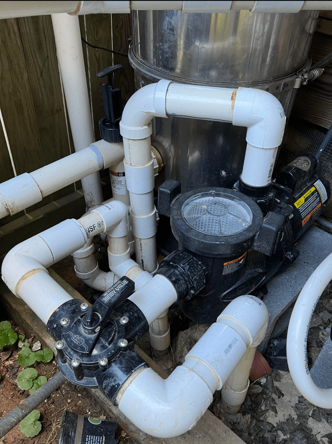
Currently, we have two inlet pipes (one for each skimmer), one return pipe at the far end of the picture. A booster pump hooked in but not in use as I've been using dolphin, so plan to remove it and may just use the booster outlet as an extra return? The DE filter needs to be changed for a newer one (got another Pentair DE for cheap, but the inlet/outlet pipe height is different from the current version). Plan to switch to MPV to replace the slide valve, also add some check valve type at the return line. The pool equipment are lower than the water level.

Pool heater is not in service so we can remove if space is needed. I quoted around a few local pool companies last year (before the patio project, so we still had the shed) and they were all very disliking that shed and said to move filter out from it entirely) but now that there is no such structure and open with a little more room, I would prefer to get the filter still in the corner if possible. There are parts that were not pool grade so schedule 40 pipes all the way for sure.

I will post a few more recent pix later (without the shed now), but would like to pick your brain about the ideas.

Thanks a lot.
full
full
 
I think we discussed some of this in your other post regarding the gas line replacement. Since you are removing the shed, I would not try to cram everything into that back corner. Try to push your pump back so you can have 10 inches of straight pipe (including the union) leading into the pump. Since you are removing the booster pump, then put the heater to the right of the pump to give you more room to clean it. If you add a heater later, you can place it in the same spot as shown.

Your main return looks to be against that back wall - so that should be between the pump and the filter.
Good idea to plumb your booster pump line as another return. Just remove those 2 flexible hoses and connect those pipes with solid PVC piping.

A MPV for the front of the DE filter is good idea. Remember to plumb in the drain line as well.
 
  • Like
Reactions: ShinDiors
So the timber under the inlet valve is still there, while the two other timers are now removed, the retaining wall is about 1 ft away from the main return line now (essentially the backwall of the shed retreated for about a foot), and the side wall of that shed now is a brick retaining wall as well. Because of the location of inlet pipes and the return pipe, how do I space the filter and pump so that the return pipe is in between (and why?). The most space I have right now for pump is still that corner since there is an existing outlet pipe to hook the backwash drain line in. If I move the pump to the other side of the return line, wouldn't that require a much longer pipe to connect from inlet pipes to the pump?

Also for the electric boxes, I recalled that one box is for polaris booster pump. Do I remove that entirely since I may not use the polaris or should I keep the control box just in case? Also, where might be a better place to put these electric boxes now that the backwall of the shed is gone, and now it is a brick retaining wall. I was thinking maybe mount them sideways to the fence side since I want to keep the extra space to access the filter at the corner otherwise the wires and everything kinda of in the way (if I keep the electric boxes in relatively same orientation, but mount to the metal fence of the retaining wall)pool equip.jpg

Here is the current layout of the equipment and pipes relative location.
 
Compared to have another heater and re-ran the gasline above ground, I probably would consider Salt water first, FWIW, so that should also require some consideration in the re-plumbing.
 
You have a lot of options there. Make sure to leave enough space between items to make maintenance easier.
Also, use schedule 40 PVC fittings and not DWV fittings - I see at least one DWV fitting in your pics. DWV fittings aren't pressure rated.
 
  • Like
Reactions: ShinDiors
Another q is, do you guys feel I need to have a dedicated pool company to do these replumbing or relocating the equipment as they understand these better than my general contractor? My GC is pretty well-around and would try saving money/future hassle for me.

And for the valves that I need in this setup. Do I need shut off valves on each of the inlet pipes or the current 3-way valve would work? Since the equipment pad is lower than water level, I had a scary moment 1st season when the return line had a leak (although i tried to plug all the holes, the water drained for 3 hours when the return line was cut before the glue can be put on), so I want to be able to shut it off for repairs. Locations of such valve (higher or lower to the ground? does it matter? check valve or other valve?) I heard about those rubber/plastic ball valve might stick down the road, and was thinking about a simple check valve (would that be problem with the pressure?) Any links of recommended parts would be helpful too.

Where do you suggest buying the pentair mpv btw? Checked Amazon and the price is already about 230-250...Geez.
 
Last edited:
Because of the location of inlet pipes and the return pipe, how do I space the filter and pump so that the return pipe is in between (and why?). The most space I have right now for pump is still that corner since there is an existing outlet pipe to hook the backwash drain line in. If I move the pump to the other side of the return line, wouldn't that require a much longer pipe to connect from inlet pipes to the pump?
Based on your original photos, my suggestion of moving the filter was to give you more room to perform maintenance It look cramped in that corner and if you are going DE you need to be able to service it annually or maybe twice a year if you have lots of debris. I see you note a retaining wall on the right - I thought that would be wide open space once you removed the shed. If you feel confident that there is room to service the DE filter with it positioned in the corner then just replace there.
I would not move the pump to the left unless you could still push it back a little to have a 10inch straight run into it which provides a consistent flow conduit into the pump suction.
Screenshot 2023-03-08 230434.jpg

I would remove the booster pump but keep the electrical box - just ensure there is no live wiring exposed. However if you decide to move all the electrical boxes then just keep what you need to run your existing equipment.
 
  • Like
Reactions: ShinDiors
Based on your original photos, my suggestion of moving the filter was to give you more room to perform maintenance It look cramped in that corner and if you are going DE you need to be able to service it annually or maybe twice a year if you have lots of debris. I see you note a retaining wall on the right - I thought that would be wide open space once you removed the shed. If you feel confident that there is room to service the DE filter with it positioned in the corner then just replace there.
I would not move the pump to the left unless you could still push it back a little to have a 10inch straight run into it which provides a consistent flow conduit into the pump suction.
View attachment 476394

I would remove the booster pump but keep the electrical box - just ensure there is no live wiring exposed. However if you decide to move all the electrical boxes then just keep what you need to run your existing equipment.
I assume that the two 90 degree turns from inlet pipes to the Jandy valves are not optimal, ideally if i have space to move the pump back a bit, it is better to have one 90 degree turn from the upright inlet pipes to the sides of the valve, then at least 10 inch straight line to feed into the pump correct? Also along the pipes, should I consider putting unions instead of simple PVC pipe and joints? Where should these unions be?

Also any recommendations on adding shut-off valves (location, types etc). into these lines given my below pool water level situation? My understanding is that the Jandy 3-way valve is my shut-off for skimmers inlet (can shut off each side and when loosened up, can turn 180 degree to shut off both inlets), I may only need an extra shut-off along the return line. Is a shut-off valve or check valve needed to prevent from water gushing back from the pool (say repairing plumbing, return line or other places). I read the further reading on valves here and it looks like Jandy check valves are not recommended to be used at downward water flow (which is exactly my return line's flow direction) however.

The cinder block was used to raise the pumps because water from the backyard would go there (low point) and I did not want to damage the pump when there was flooding.

The electric boxes were mounted on the wooden shed, so they are now unscrewed and put aside (with wires connected) when the shed was removed. In this case, would it still be your suggestion to remove the polaris timer/control box entirely along with the booster pump? Would it be easy to hook it back up (electric control wise) if needed?
 
Last edited:
I assume that the two 90 degree turns from inlet pipes to the Jandy valves are not optimal, ideally if i have space to move the pump back a bit, it is better to have one 90 degree turn from the upright inlet pipes to the sides of the valve, then at least 10 inch straight line to feed into the pump correct? Also along the pipes, should I consider putting unions instead of simple PVC pipe and joints? Where should these unions be?

Also any recommendations on adding shut-off valves (location, types etc). into these lines given my below pool water level situation? My understanding is that the Jandy 3-way valve is my shut-off for skimmers inlet (can shut off each side and when loosened up, can turn 180 degree to shut off both inlets), I may only need an extra shut-off along the return line. Is a shut-off valve or check valve needed to prevent from water gushing back from the pool (say repairing plumbing, return line or other places)
Most equipment pads require the use of 90 deg elbows as almost impossible to avoid them. Where you need to “bend“ a line for alignment or to avoid hitting another line, you can use 45 deg fittings like I showed in the drawing.
The purpose of a 3-way diverted valve is to balance flow between 2 pipes but not be able to completely shut off flow as that could damage the pump. Applies both to suction side and return (pressure) side. While you can “trick” a 3 way valve to close off incoming flow you really should not do that. On the 3-way valve one of the 3 connections is marked “inlet“ and that connection should not be able to be closed off. The other 2 can be closed off but only 1 or the other - so never can both those remaining 2 pipes be closed or another way of saying it - one pipe is always open.

Some people avoid the use of a 3-way diverted valve and instead, use a 2-way diverted valve on each pipe. This provides independent control and allows you to balance flow, it also allows the risk of having both valves closed at the same time and could damage the pump.

Depending on your pump being above or below the level of the pool, check valves can help. For example, a check valve located along the 10 inches of straight pipe leading into the pump can close when the pump turns off and it holds water in the pump basket to allow for easier priming when the pump restarts on the next schedule.

You should use a union on both sides of the pump which facilitates the removal of the pump if needed for repair or if you close your pool for winter you can move the pump to a dry area for storage. If you have a SWCG, they come with unions on both sides. The filter and heater have unions on the inlet and outlet pipes to facilitate installation so you do not have to glue solid pipe between 2 fixed objects.

I would not hook up the electrical panel for a booster pump if you plan to remove the old booster pump. It just adds complexity.

It is best to draw out a plumbing diagram with all the fittings and unions you think you need. Then you will dry fit them just to ensure they all match before you start to glue them. Do in stages. Go from your 2 suction pipes to the pump. See how that looks. Then go from the pump to the filter or to the MPV you plan to use. Continue that progression taking into account where your suction pipes are located and where your return pipes are located. Those are your fixed points you have to tie into.
 
  • Like
Reactions: ShinDiors

Enjoying this content?

Support TFP with a donation.

Give Support
@HermanTX @ajw22 @Texas Splash @PoolGate
So I marked up the current thinking of plumbing, with the booster pump and heater out of the picture.

First clarification, in my current setup, the pipe bends twice 90 degree then feed into the 3-way valve. I assumed that was due to the space limitation of where the pump could be and the need of the 10 inch straight pipe before pipe (the extra bend is to create the 10 inch straight line). Now that I have a bit more space, I should be able to only bend one 90 degree and goes directly to each side of the 3-way valve (like in the pix below, right corner)?

And for the return line, since I would like to plumb the existing one for polaris into an additional return, I should put a check valve before it branches out to main return line and additional return line right? Is this the correct valve to be used? Or should I use a Jandy neverlue two way valve?

For the unions, can I use regular schedule 40 ones like this? And the union between pump and filter should be before mpv or after mpv?

I think I will still use the Jandy 3-way valve instead of the individual 2-way valves. I was told the "hack" by the pool guy to turn that handle 180 degree to turn off both inlets and aware of the potential damage if the pump got turned on in that case.

Schedule 40 PVC pipes and joints can be bought at HD, and the only parts I should prepare from other venders are the
pentair 2inch mpv, and a Jandy check valve correct? Looks like my fixed points (two suction inlets and two pressure outlets) are 1.5 inch, but we would like to do 2 inch pipes in between I suppose.

plumbing.jpg
 
@HermanTX @ajw22 @Texas Splash @PoolGate
So I marked up the current thinking of plumbing, with the booster pump and heater out of the picture.

First clarification, in my current setup, the pipe bends twice 90 degree then feed into the 3-way valve. I assumed that was due to the space limitation of where the pump could be and the need of the 10 inch straight pipe before pipe (the extra bend is to create the 10 inch straight line). Now that I have a bit more space, I should be able to only bend one 90 degree and goes directly to each side of the 3-way valve (like in the pix below, right corner)?

And for the return line, since I would like to plumb the existing one for polaris into an additional return, I should put a check valve before it branches out to main return line and additional return line right? Is this the correct valve to be used? Or should I use a Jandy neverlue two way valve?

For the unions, can I use regular schedule 40 ones like this? And the union between pump and filter should be before mpv or after mpv?

I think I will still use the Jandy 3-way valve instead of the individual 2-way valves. I was told the "hack" by the pool guy to turn that handle 180 degree to turn off both inlets and aware of the potential damage if the pump got turned on in that case.

Schedule 40 PVC pipes and joints can be bought at HD, and the only parts I should prepare from other venders are the
pentair 2inch mpv, and a Jandy check valve correct? Looks like my fixed points (two suction inlets and two pressure outlets) are 1.5 inch, but we would like to do 2 inch pipes in between I suppose.

View attachment 476794
You want to have the pump union on either side of the pump. One side of the union screws into the pump. See the link but ensure you have the right size threads for your pump.

It is best to use 2” PVC throughout the equipment pad as majority of equipment connections are that size.
On the suction - you would put the 3-way valve between the 2 returns so you can select either one or the other or both for suction.
If you install a check valve which you linked to then put that between the 3-way valve and the pump union.

The MPV connects to the filter with its unions. You do not need to add unions where the 2” pipe connects to the MPV unless you wish to. I would avoid using unions from HD as they tend to be bulky. You could use sweep elbows rather than standard 90 deg elbows but they need to purchased at a dedicated plumbing store. See this thread on post #59 for what a sweep elbow looks like. Also, you need a little more room for them to be used. Ensure they are sch 40 pipe.

You can just put a Tee to connect your main return line and the previous dedicated pump line. There is no need to add a 2-way valve or check valve.

Also your drawing is not fully accurate as your exit from the filter is from the MPV, not a separate line as you show.
The MPV connects to the inlet and exit connections of the filter (this uses Pentair specific unions). Then the MPV has an inlet from the pump, an outlet to the return line and an outlet to the drain line. Ensure you connect the right pipes to the proper connections.

If you purchase your fittings from HD then ensure everything is sch 40. Sometimes fittings get mixed with the drain & waste fittings even though they are in different sections.
 
  • Like
Reactions: ShinDiors
"You can just put a Tee to connect your main return line and the previous dedicated pump line. There is no need to add a 2-way valve or check valve."

I wanted this because my pad is below the water level and this happened once. It could be that I did not plug the returns (and polaris return) too well, but it was nerve wracking to have to wait for 3 hours for the water to slow down enough to glue the joint back on in the return lines.

I am looking at Jandy 4724 neverlube 2-way valve (instead of check valve) and put one on each return (main return and previous polaris return) or a 3-way at the Tee. I'm not looking at balancing return flow for anything fancy like water feature, just need to make sure when necessary I have something to prevent pool water from backing up.

I'm debating on weather to just use a 2-way divert valve before the T, or 3-way at the T, or two separate 2-way at each return lines after the Tee. I actually cannot think of a scenario that would require me to turn off one return line only since these two return lines (existing return+polaris repurposed return) are branched out from a single pipe from the filter, so they are connected. It seems the benefit of having two individual 2-way valves originated from their location being closer to the ground (compared to at or before the Tee). rather than the capability of individually shut-off? If anything breaks above the valve on one line but before the Tee, I would still need to shut both return lines to avoid water from backing up from the other return line. If I put a single 3-way at the Tee or a 2-way before the Tee, those won't help for anything after the Tee branching out into the two lines.

If most likely usecases of having to shut-off return flow is for repair/service stuff before the Tee, for example, the filter, pump etc, then a check valve or a 2-way before the Tee would just be enough. The individual shut-off valves on each return line won't help me much unless the pipe between Tee and valve broke, anything below the valve still suffer from the fact that the water will gushing up from the underground plumbing until it levels with the break point ( more water, if return jets in the pool not plugged tight enough).

Apologize that I may have overthought it, just trying not to unnecessarily overcomplicate the simple plumbing. (more parts, more places to fail).
 
Last edited:
"You can just put a Tee to connect your main return line and the previous dedicated pump line. There is no need to add a 2-way valve or check valve."

I wanted this because my pad is below the water level and this happened once. It could be that I did not plug the returns (and polaris return) too well, but it was nerve wracking to have to wait for 3 hours for the water to slow down enough to glue the joint back on in the return lines.

I am looking at Jandy 4724 neverlube 2-way valve (instead of check valve) and put one on each return (main return and previous polaris return) or a 3-way at the Tee. I'm not looking at balancing return flow for anything fancy like water feature, just need to make sure when necessary I have something to prevent pool water from backing up.

I'm debating on weather to just use a 2-way divert valve before the T, or 3-way at the T, or two separate 2-way at each return lines after the Tee. I actually cannot think of a scenario that would require me to turn off one return line only since these two return lines (existing return+polaris repurposed return) are branched out from a single pipe from the filter, so they are connected. It seems the benefit of having two individual 2-way valves originated from their location being closer to the ground (compared to at or before the Tee). rather than the capability of individually shut-off? If anything breaks above the valve on one line but before the Tee, I would still need to shut both return lines to avoid water from backing up from the other return line. If I put a single 3-way at the Tee or a 2-way before the Tee, those won't help for anything after the Tee branching out into the two lines.

If most likely usecases of having to shut-off return flow is for repair/service stuff before the Tee, for example, the filter, pump etc, then a check valve or a 2-way before the Tee would just be enough. The individual shut-off valves on each return line won't help me much unless the pipe between Tee and valve broke, anything below the valve still suffer from the fact that the water will gushing up from the underground plumbing until it levels with the break point ( more water, if return jets in the pool not plugged tight enough).

Apologize that I may have overthought it, just trying not to unnecessarily overcomplicate the simple plumbing. (more parts, more places to fail).
I would put a 2-way diverted valve on each of the 2 return lines and place them close to the ground or where the pipe connects back to the 1.5” return. You will only use them to prevent flow from the pool to the equipment pad. You would need to do that when you add your SWCG or if you need to clean your filter.

I think you plan to put a 2-way diverted valve on the pump suction line before the union. This way, with the 3 2-way diverted valves you can close off any flow from the pool to the equipment pad. this will allow you to do any maintenance work needed.

Your SWCG (in the future) should be placed before the Tee on your return line (before the original return and the Polaris converted return). coming from the filter (MPV connection). A SWCG is about 14-17 inches (depending on model and including unions) so plan for that piece of straight pipe when you do your initial plumbing.
 
  • Like
Reactions: ShinDiors
@HermanTX Thanks so much for your patience and it's been very helpful.

Just one quick clarification, so I should use this model of valve for return line locations(return pipes are 1.5" and 1"), and this between 3-way and union before the pump (since the pipe would be 2" there) right? Also where can I buy sch40 unions that are not bulky like HomeDepot’s?

Are you suggesting not to use the 3-way as a suction side shut-off, only use it as "divert", but rely on the 2-way added behind it as the shut-off valve for water coming into the pump? Does the "trick" of turning the 3-way handle 180 degree not really work to shut off both inlets at the 3-way or it's just a concern of possible negligence of not switching them back before turning pump back on and damage the pump?
 
Last edited:
@HermanTX Thanks so much for your patience and it's been very helpful.

Just one quick clarification, so I should use this model of valve for return line locations(return pipes are 1.5" and 1"), and this between 3-way and union before the pump (since the pipe would be 2" there) right? Also where can I buy sch40 unions that are not bulky like HomeDepot’s?

Are you suggesting not to use the 3-way as a suction side shut-off, only use it as "divert", but rely on the 2-way added behind it as the shut-off valve for water coming into the pump? Does the "trick" of turning the 3-way handle 180 degree not really work to shut off both inlets at the 3-way or it's just a concern of possible negligence of not switching them back before turning pump back on and damage the pump?
The 2 inch x 1.5 inch valve (#4724) allows you to put a straight piece of 1.5” PVC pipe into the valve connection or you need to put a 2” coupler on the valve connection then put in 2” pipe into that connection. So if you have 1.5” facing up from the ground then you can put the valve directly on that 1.5“ pipe then use 2” coupler on the other side then run 2” PVC from there to your filter. Once you open the valve, remove the handle so only you can control whether the valve is open or closed.

On the suction side, I think you indicated that was also 1.5” pipe. So use a slip reducer fitting that goes from 1.5” to 2”. Come up to the Tee junction where you will insert the 3-way valve. Use the Jandy 4717 3-port 2”x2.5” valve. This allows you to insert straight 2” pipe into its connections.

I would NOT try to turn the handle on the 3-way handle to block the flow to the pump. That is not how the valve is to operate. You risk someone not knowing how the valve is set up to inadvertently turning the valve. By placing a Jandy 4716 2- port 2”x2.5” valve in the straight run to the pump (the 2” pipe goes directly into the valve connection) gives you the capability to block the flow from the pool. Once you open the valve then remove the handle so no one closes the valve. Therefore you have control of when the valve is open or closed.

So the 3 2-port valves are only controlled by you after you remove the handle. The handle for the 3-port valve can stay on the valve and allow you to balance the flow of the 2 suction pipes.

See my crude drawing.

891CA858-B637-400B-AF1D-EC32A626F404.png
 

Attachments

  • Basic Schematic.pdf
    302.6 KB · Views: 4
  • Like
Reactions: ShinDiors
Thanks for the further clarification.

Do you suggest using those Hi-temperature Unions at the pump as listed here.

Questions about different type of sch40 parts
1. Plan to use this for the Tee from filter to returns. Then a reducer to 1 inch (polaris return) after the 2-way valve's 1.5" outlet.
2. Plan to use the cmt hi-temp unions for the pump inlet and outlet
3. What type of unions should I pick for anything in between, this or this? I think I do not need unions at the filter right? because the inlet and outlet are connected via unions to mpv. Do I need a union between MPV and return Tee (for future swg) or just need a straight pipe longer than 16-17' to have enough space for the swg? Does SWG need to be installed horizontally or vertically (for examples, do I need to bend the pipe from mpv down a bit to connect the Tee at lower height?)
4. Any other specialty sch40 stuff I need to prepare other than from HD?

Thanks a lot.
 
Last edited:
Thanks for the further clarification.

Do you suggest using those Hi-temperature Unions at the pump as listed here.

Questions about different type of sch40 parts
1. Plan to use this for the Tee from filter to returns. Then a reducer to 1 inch (polaris return) after the 2-way valve's 1.5" outlet.
2. Plan to use the cmt hi-temp unions for the pump inlet and outlet
3. What type of unions should I pick for anything in between, this or this? I think I do not need unions at the filter right? because the inlet and outlet are connected via unions to mpv. Do I need a union between MPV and return Tee (for future swg) or just need a straight pipe longer than 16-17' to have enough space for the swg? Does SWG need to be installed horizontally or vertically (for examples, do I need to bend the pipe from mpv down a bit to connect the Tee at lower height?)
4. Any other specialty sch40 stuff I need to prepare other than from HD?

Thanks a lot.
OK on step #1
OK for Step #2. I have used these unions for the pump. Or you can use these type.
For step #3 I do not think you need any further unions in middle of pipe. When you are ready for SWCG you will need to cut pipe to put in the SWCG with its unions.
SWCGs can be installed either horizontally or vertical depending on space. I like horizontal but if you have limited space then vertical is fine. The Pentair IC SWCG should be installed on the vertical leg flowing upwards. Some other SWCGs can be installed on the downward flow leg If they have a separate flow switch that can be placed elsewhere. Just check the manual when you decide which SWCG you purchase.
For Step #4 - I have used reducers, elbows and tees from HD as well as straight pipe. Their unions are a little bulky but I do not think you need any of them anyway. Just ensure they are sch 40 because people just throw any fitting back in a box so don’t trust the box label. I always check the price label on the fitting itself.
 

Enjoying this content?

Support TFP with a donation.

Give Support
Thread Status
Hello , This thread has been inactive for over 60 days. New postings here are unlikely to be seen or responded to by other members. For better visibility, consider Starting A New Thread.