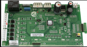
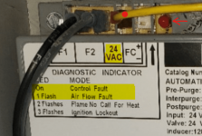
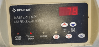
Pentair Mastertemp 400 - Not igniting No errors
- Thread starter delyles
- Start date
You are using an out of date browser. It may not display this or other websites correctly.
You should upgrade or use an alternative browser.
You should upgrade or use an alternative browser.
The AFS (Air Flow Switch) might be stuck closed.
Disconnect the blue wires from the AFS and check the switch contacts for continuity.
There should not be any continuity between the contacts if the blower is not on.
If the contacts are not O.L (Open Line), then the switch is likely to be bad.
Disconnect the blue wires from the AFS and check the switch contacts for continuity.
There should not be any continuity between the contacts if the blower is not on.
If the contacts are not O.L (Open Line), then the switch is likely to be bad.
The AFS should be open before the blower starts and then it should close within a second or two from when the blower starts.
If the AFS is closed before the blower starts, the system knows that the AFS (Air Flow Switch) is bad and the blower will not turn on and you should get an AFS light on the control board or a “Control Fault” LED on the Fenwal ICM.
You can disconnect the wires from the AFS to see if the blower will start.
If the blower starts and there is good airflow from the exhaust, you can connect the AFS wires and the heater should start.
This is risky starting the heater with jumped AFS wires, so do not do this without good airflow and only allow the heater to run for a few seconds.
In fact, do not do this test at all due to the risk.
If the AFS is bad, just replace the AFS and then see what happens.
Last edited:
swamprat69
Well-known member
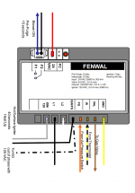
I see that you are correct. That specific Fenwal 35-66 seems to operate in the same manner, but with different labeling on the terminals. The TH terminal is activated by the pressure switch (PS) closing but is not labeled PS and the blower is activated by a call for heat at the IND terminal but is not labeled TH, but both controls seem to operate in the same manner.
Once the Air Flow Switch closes, the TH terminal get 24 VAC to activate the HSI (Hot Surface Ignitor).The TH terminal is activated by the pressure switch (PS) closing but is not labeled PS
The pressure switch (PS) has to be closed before the heater will send the signal to start the blower.
To start the blower, 24 VAC is sent to the IND (Inducer/Blower) terminal of the Fenwal Ignition Control Module.
This closes the relay between the F1 and F2 terminals on the Fenwal Ignition Control Module, which sends power to the blower.
If the blower starts, the AFS should close.
Once the Air Flow Switch closes, the TH terminal gets 24 VAC to activate relays that power the HSI (Hot Surface Ignitor).
After 20 seconds, the VAL terminal sends 24 VAC to pin 5 of the J1 connector, which then goes to pin 1 of the J3 connector.
Pin 1 of J3 goes to the AGS (Automatic Gas Shutoff) sensor.
The AGS is normally closed and the 24 VAC returns to pin 2 of the J3 connector.
24 VAC then goes from pin 5 of the J3 connector to the gas valve.
Last edited:
swamprat69
Well-known member
I think that we are getting crossed because of the different connection labels on the Fenwal. On furnaces and boilers where a Fenwal is used for ignition (PS) is the designation for the air pressure switch and there is no water pressure switch. Yes the AFS has to be open for the blower/inducer to power up when 24V is applied to IND as that is a safety feature in event of an air pressure switch that is stuck closed.
This Jandy matches up more with what you are describing.I think that we are getting crossed because of the different connection labels on the Fenwal. On furnaces and boilers where a Fenwal is used for ignition (PS) is the designation for the air pressure switch and there is no water pressure switch. Yes the AFS has to be open for the blower/inducer to power up when 24V is applied to IND as that is a safety feature in event of an air pressure switch that is stuck closed.
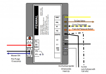
swamprat69
Well-known member
Pretty much the same thing with different labeling. They both operate internally in the same way. The labeling of the terminals goes back to original HVAC labeling. Thermostat labeling is color coded: R (red) = 24V hot, W (white) = call for heat, Y (yellow) = call for cooling, G (green) = call for fan, C ( other than R,W,Y or G, but most commonly black or blue) = 24V common. You get an alternative W designation of TH from the common gas valve terminal designations of TH = call for heat, TH/TR = simply a connection terminal with no internal connection to the gas valve itself which is used for inserting safeties into the circuit before connecting the 24V hot to the TH terminal of the gas valve and TR = 24V common. In the case where the W/TH terminal is labeled IND, it is labeled as such because of the action that it causes to happen ( but only after checking that 24V is not present at at PS, which is now labeled TH) , but the 24V signal at IND is still the call for heat from the heater electronic control board and the 24V signal at TH is still proof that the (air) pressure switch has closed after the inducer has started. Also just for clarification if the fan/blower used to aid combustion is on the outlet side of the combustion chamber it is an induced draft blower and if it is on the inlet side of the combustion chamber it is a combustion air blower. F1 and F2 are the normally open relay contacts for one leg of the induced draft/combustion air blower. In older natural draft furnaces the call for heat from the thermostat W went either to TH/TR terminal of the gas valve and through the safeties to the TH terminal of the gas valve or through the safeties connected on the furnace control board to the TH terminal on the gas valve.
Thread Status
Hello , This thread has been inactive for over 60 days. New postings here are unlikely to be seen or responded to by other members. For better visibility, consider Starting A New Thread.


