Pentair Mastertemp 250 Heater Problem

neergmot

Member
Mar 7, 2025
6
Florida
Hello, new here and after lots of google searches decided to ask for help. I have a Pentair Mastertemp 250 gas heater that I’m having issues with. I am thinking the issue is with the gas valve. I’ve replaced the gas valve and the control board but am still having the issue.

I get 24v to the wires going to the valve when not connected. When the wires are connected, the voltage drops to 9v and I never smell gas when it’s supposed to open. I’ve tried 2 different gas valves and get the same result. What could cause the voltage drop of the valve is good?

Thanks in advance!
 
Welcome to TFP.

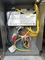
The gas valve voltage runs through a relay in the Fenwal. We have seen bad relays in the Fenwal. You need to check if you have 24V into the relay.

The blower (Inducer) starts when 24 VAC is sent to the IND (Inducer) terminal. Verify 24 VAC from IND to GND. This closes the F1 to F2 relay.

Once the blower pressure switch closes, 24 VAC is sent to the TH terminal. Verify 24 VAC from TH to GND. This closes the L1 to S1 and L2 to S2 relays, powering the ignitor with 120 volts.

The gas valve opens when 24 VAC is sent to the VAL terminal at about 20 seconds after the ignitor is powered.

See...

Thank you for the welcome and the quick reply.

Here is what I get:

TH to GND = 22.5v
IND to GND = 22.5v
VAL to GND = 9v with valve wired up and 22v without valve wired up

Thanks
 
Do you hear the click of the gas valve opening?

You need to connect a manometer to the gas valve and check the gas pressures.

Did you replace the PCB with a genuine Pentair board?

Show me a picture of both sides of the PCB.
 
Do you hear the click of the gas valve opening?

You need to connect a manometer to the gas valve and check the gas pressures.

Did you replace the PCB with a genuine Pentair board?

Show me a picture of both sides of the PCB.
No sound from the gas valve. The originaI valve did click. Replaced with a know good used valve, no sound but same voltage drop. Now have replaced with branded new valve, same thing. All of this was with old PCB. New PCB now but same voltage drop, no noise. I have 8” pressure but it never changes. I never smell gas.

No, aftermarket PCB board. Can take a picture shortly.
 
Do you still have the original valve that clicked?

We have seen many problems with aftermarket PCBs not working correctly.

I think the 9V is the normal voltage drop from the relay coil resistance.

I would put back in the original gas valve and PCB.

What was the original problem?
 
Do you still have the original valve that clicked?

We have seen many problems with aftermarket PCBs not working correctly.

I think the 9V is the normal voltage drop from the relay coil resistance.

I would put back in the original gas valve and PCB.

What was the original problem?
Original PCB has corrosion.

Original problem was the heater wouldn’t ever ignite, Fenwal would flash 3 times eventually. Replaced igniter, same thing. Measured gas pressure and noticed it never dropped, also noticed I never smell gas so assumed it was a gas valve issue.
 
It becomes very difficult to diagnose problems with aftermarket PCBs. Many threads here discuss how simply installing a genuine Pentair PCB fixes things.

Your problem may be the PCB, the Fenwal, or your gas pressure. I doubt it is the gas valve after two of them.

If you have a 24V AC transformer, you can connect it to the gas valve and see if it clicks and you smell gas. You can also check the voltage when connected.
 
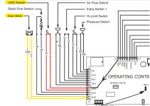
24 VAC leaves the VAL Terminal on the Fenwal ICM (Ignition Control Module) and goes to Pin 5 of J1.

It then goes to Pin 1 of J3 --> red wire to the AGS Sensor --> red wire back to --> Pin 2 of J3.

24 VAC then leaves Pin 5 (Yellow wire) and Pin 6 (Yellow Wire with white stripe) of J3 to the gas valve.

Note: The Yellow Wire with white stripe is considered to be ground.

There is probably a short in the wires, gas valve or AGS sensor.

Check the resistance of the AGS Sensor; it should be very low ohms.

Check all wires for resistance.

Most likely, there is excessive resistance causing a voltage drop.

Check for a short to ground or damaged wires.

Check the valve coil resistance.

Measure the current going to the gas valve.


1741390065054.png


1741391109050.png

IMG_6526.jpg
 
Last edited:

Enjoying this content?

Support TFP with a donation.

Give Support
24 VAC leaves the VAL Terminal on the Fenwal ICM (Ignition Control Module) and goes to Pin 5 of J1.

It then goes to Pin 1 of J3 --> red wire to the AGS Sensor --> red wire back to --> Pin 2 of J3.

24 VAC then leaves Pin 5 (Yellow wire) and Pin 6 (Yellow Wire with white stripe) of J3 to the gas valve.

Note: The Yellow Wire with white stripe is considered to be ground.

There is probably a short in the wires, gas valve or AGS sensor.

Check the resistance of the AGS Sensor; it should be very low ohms.

Check all wires for resistance.

Most likely, there is excessive resistance causing a voltage drop.

Check for a short to ground or damaged wires.

Check the valve coil resistance.

Measure the current going to the gas valve.


View attachment 631090


View attachment 631091

View attachment 631092
Thank you for all the info. I’ll check all this in the morning and report back.
 
  • Like
Reactions: JamesW
I think that, most likely, the AGS Sensor is failing and has high resistance.

Disconnect both red wires and check the resistance of the AGS Sensor.

It should be close to 0 OHMs.

If higher than a few ohms, replace it.

1741395748977.png
 
I get 24v to the wires going to the valve when not connected. When the wires are connected, the voltage drops to 9v
You should get 24 VAC across the Gas Valve.

So, you are missing 15 VAC.

Put 1 meter lead on the red dot at the Fenwal ICM Valve Terminal and the other lead at the terminals of the AGS Sensor individually.

The Voltage from the VAL Terminal to anywhere in the path to the gas valve should read 0 VAC (Difference) because the resistance should be close to 0.

If you get 15 volts, then you know that there is high resistance between the two points.

1741399276250.png


1741399445453.png
 
Test Voltage from the ICM VAL Terminal to the Red, Blue, Green and Purple Dot.

The Voltage when the gas valve is powered should be 0 between the Fenwal ICM VAL Terminal and each point.

If you get 1 to 15 volts, then you know that the resistance is between the points.

Try testing at the AGS switch first as it is easiest to get to.

The wires have to be connected and the voltage needs to be going to the gas valve.

The gas valve should get 24 VAC about 20 seconds after the blower starts.

The voltage will not be on for long if there is no ignition because there will be no Flame Rectification and the voltage will be shut off in 7 seconds.

1741399812115.png
1741401496010.png
 
Last edited:
The easiest place to test is at the brown dots, which is where the red wires connect to the AGS Sensor.

If you get 0 VAC at one brown dot and 15 VAC at the other brown dot (Measured from the ICM VAL Terminal), then you know that the AGS Sensor is the problem.

Or, test from brown dot to brown dot and you should get 0 volts if the AGS sensor is good and some voltage if it is defective.

You have to test when voltage is going to the gas valve which is about 20 to 27 seconds after the blower starts.


1741400908225.png
 
Last edited:
24 VAC comes from the transformer to Pins 3 and 4 (ground) on J7 and to pins 1 and 2 (ground) on J1.

24 VAC leaves pins 1 and 2 (ground) on J1 and goes to the top 24 VAC terminal on the Fenwal ICM and the Ground terminal on the Fenwal ICM.

The Fenwal ICM sends 24 VAC to the VAL terminal on the ICM using a relay and that goes to Pin 5 on J1 (Yellow with red stripe).

You can check for voltage between the top 24 VAC terminal on the Fenwal ICM and the VAL terminal on the ICM when the gas valve is powered.

If the resistance is low, the voltage should be at 24 VAC at both terminals and this will read as 0 volts AC.

If the voltage reads high, then the resistance is likely in the Fenwal.

1741460481049.png


1741459798208.png

1741459596326.png

Fenwal.png

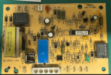
The two black boxes are relays.

The top box is the blower relay.

The black box on the right is the valve relay.

The blue box is the ignitor relay.

1734654772072.pngFenwal.png
 
24 VAC comes from the transformer to Pins 3 and 4 (ground) on J7 and to pins 1 and 2 (ground) on J1.

24 VAC leaves pins 1 and 2 (ground) on J1 and goes to the top 24 VAC terminal on the Fenwal ICM and the Ground terminal on the Fenwal ICM.

The Fenwal ICM sends 24 VAC to the VAL terminal on the ICM using a relay and that goes to Pin 5 on J1 (Yellow with red stripe).

You can check for voltage between the top 24 VAC terminal on the Fenwal ICM and the VAL terminal on the ICM when the gas valve is powered.

If the resistance is low, the voltage should be at 24 VAC at both terminals and this will read as 0 volts AC.

If the voltage reads high, then the resistance is likely in the Fenwal.

View attachment 631186


View attachment 631185

View attachment 631184

View attachment 631187

The two black boxes are relays.

The top box is the blower relay.

The black box on the right is the valve relay.

The blue box is the ignitor relay.

View attachment 631188View attachment 631189
This is really great info, thank you for being so thorough.

For the below, I get 22v when the valve is being called to open


You can check for voltage between the top 24 VAC terminal on the Fenwal ICM and the VAL terminal on the ICM when the gas valve is powered.

If the resistance is low, the voltage should be at 24 VAC at both terminals and this will read as 0 volts AC.“

Should I order a Fenwal now or should I test further?
 
The gas valve only gets power for 7 seconds if there is no ignition.

The power starts at about 20 seconds after the blower starts, so you have to test in that 7 second window.

Get a separate cheap voltmeter to put on the gas valve to see the power start and stop.

Use meter lead alligator clips to make it hands free.
 

Enjoying this content?

Support TFP with a donation.

Give Support