Pentair Intelliflow pump running on schedule but at zero watts

emailrob

Member
Mar 3, 2024
6
Southern California
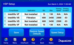
Hello all, first time poster. I searched across the forums but couldn't find anything directly relevant. I use iAqualink and a Pentair Intelliflow i2. I can connect via wifi no issues using the wifi module. When I use the web interface I can turn on the Pentair OK.

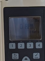
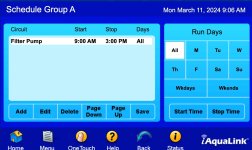
It's been running great for about 6 months but we had a power cut. Since then, everything rebooted OK but it won't run to schedule. It says 'running schedule', but its running at 0RPM.

It will run a quick click by clicking the button fine.

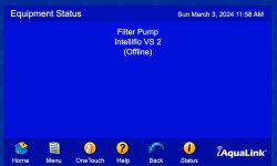
In the status it says
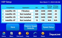
Filter Pump
Intelliflo VS (offline)

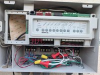
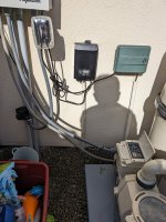
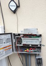
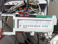
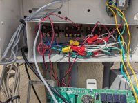
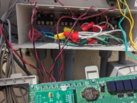
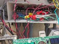
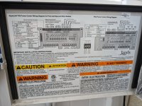
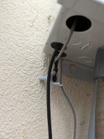
Any ideas on where to start? I posted some pictures of the current stage and any errors.

Thanks in advance.
 

Attachments

  • 2024-03-03_11-57-41.jpg
    2024-03-03_11-57-41.jpg
    245.6 KB · Views: 10
  • 2024-03-03_11-58-02.jpg
    2024-03-03_11-58-02.jpg
    96 KB · Views: 12
Why is the pump listed as the #2 ? It should be #1 as the pump identifier.
Was this how it was set up? Do you use a RS485 cable from the pump to the AquaLink RED connector?

@MSchutzer or @PoolGate may have some ideas
 
Thanks very much for the reply, I switched them so the pump is showing as #1. I may have switched them accidentally when I was trying to fix it.

The pump is connected via a cable. I checked all the connections inside the aqualink and they seem to be seated OK. I can communicate between the aqualink and the pump itself (turn it on and off) but it won't run a schedule.

Here's a pic from inside the aqualink in case it makes a difference.

The status page still says

Filter Pump

Intelliflo VS 1

(Offline)
 

Attachments

  • Photo March 6.jpg
    Photo March 6.jpg
    368.7 KB · Views: 7
I do not see where the pump RS485 cable is connected to the RED connector. I only see the 4 wire connection that appeas to be an antenna.
Also, is your VS pump receiving constant power? It appears the pump power cables are on the LOAD side connections of the filter pump relay (First Relay on the Left).
What other equipment do you have connected to the AquaLink? I see 4 (maybe 5) conduits entering the box from the bottom - what does each of those go to? A blower? A heater? A Pump?

You mentioned it was running for 6 months before this electrical issue. How was the schedule set? Can you do a picture of your Schedule screen and also a picture of the Pump Speed screen (that would be the screen when you hit the button that says Speed Setup on the VSP Pump setup).
 
@HermanTX is correct, first thing first, when you turn the pump off via the RS panel is the control panel on the Intellifo still lit up, or does it power down? The VS pump should be receiving constant AC power.

He's also right in there appears to only be one thing connected to the red RS-485 connector.

I suspect that your VS pump was never set up to be speed controlled via the Aqualink system, but rather had it's schedule (number of hours to run which speeds) set up on the pumps control panel and then the Aqualink system just closed the filter/pump relay and applied AC power to the pump. The pump woke up and ran it's schedule based on its control panel.

That's not the correct way to set up an Intelliflo VS to operate with the Aqualink system.

To set the VS pump up for operation via the speed tables in the Aqualink system you need the following:
1. The pump needs to be connected to constant AC power, the pump AC should be wired directly to the pump breaker and the filter/pump relay should be bypassed.
2. You need to connect the RS-485 cable from the pump to one of the red RS-485 connectors on the RS panel.
3. You need to determine what the pump's address is set to via the control panel of the pump. The default is one unless it has been changed. You need to verify what the address is set to.
4. Then you need to set up an Intelliflo VS pump on the appropriate address for pump1 to pump4 on the VSP speed setting window, and set the application for filtration. Pump1 corresponds to pump address 1, pump2 to pump address 2, and so on. The pump address and the pump number you set up in the Aqualink system need to match.
5. And lastly you will need to go into the speed table for the pump number that you set up and set up the speeds you want the pump to run.

Please verify that you have a RS-485 cable from the pump connected to the RS panel and make sure the pump is getting AC power even when the pump is off.

I don't think your pump was ever set up correctly.
 
  • Like
Reactions: HermanTX
Thanks for the detailed reply. Here is a photo with a wider shot - there is a cable from the pump to the box which I assume is the RS-485. It's the one ziptied onto the grey cable.

The pump was historically (as of a month or so ago) able to be controlled using a schedule on the iaqualink website/app. It ran fine for months, turning on at the right time , priming, running for 6 or 8 hours, and then turning itself off. But something happened (maybe when we had a brief power cut) and now it only turns on but does not run the pump itself.

The schedule I have turns the pump on at 9am (the display is blank until then), and the display turns on. But it comes on at 0RPM/0 Watts and 'stopped'. That's the part I'm trying to figure out why it seemed to turn on using the schedule, but doesn't actually start the pump (although it is giving it power).

(note - the pump still runs fine if I press 'quick clean').

Robert
 

Attachments

  • Photo Mar 7 2024.jpg
    Photo Mar 7 2024.jpg
    685.5 KB · Views: 4
  • Original March 7 Photo.jpg
    Original March 7 Photo.jpg
    316.8 KB · Views: 4
  • Photo March 7 2024.jpg
    Photo March 7 2024.jpg
    60.1 KB · Views: 4
Where does that small diameter gray wire go to the AquaLink box that is coming from the pump? The picture of the PCB only showed 1 wire connected to the RED connector which is 4 wires and must be the antenna.
Show a picture of where it is wired to the pump and another where the other end is wire to the PCB.
If AquaLink is controlling the pump then the display would say - DISPLAY NOT ACTIVE
See photo of my Pentair pump which is connected to AquaLink

Also, you state that you press the Quick Clean button indicates the pump is under self control and not with the AquaLink

I cannot comment on how it was working for 6 mos but it clearly does not appear now that the AquaLink is controlling the pump.
Also, it was requested that you show a screenshot of your Schedule screen and the Pump Speed Setting screen as that will help us help you.
IMG_1342.jpeg
 
  • Like
Reactions: Jimrahbe
Rob,

All IntelliFlo VS pumps are designed to get constant AC power, they should not be turned on and off by your Pump/Filter relay. That is not the problem now, but something to keep in mind..

It sounds like you have lost your com port (RS-485)... I suspect that the pump is the only thing on the com port, so unless the pump did not run, you would never know if the com port is working or not. Do you have anything else the uses the RS-485 com port?

The display on the pump will show "Display not active" if the com port is working. It could be a bad chip in the pump, or it could be a bad chip in your automation. Could be a bad cable.. Since I don't know anything about your automation, I guess it could be that it lost its programming..


Thanks,

Jim R.
 
Thanks, appreciate the replies. Sorry for the delay in replying - I've been travelling for work.

Here are the photos. I highlighted where the wiring from the pump goes to also.
 

Attachments

  • 2024-03-11_09-05-31.jpg
    2024-03-11_09-05-31.jpg
    172 KB · Views: 7
  • 2024-03-11_09-05-44.jpg
    2024-03-11_09-05-44.jpg
    245.2 KB · Views: 7
  • Photo March 11.jpg
    Photo March 11.jpg
    679 KB · Views: 7
If you look at the schematic on the door (on left side of photo) you can see that the GREEN connector is for use for the Air, Water & Solar sensors and the Heater control. Whoever connected the RS485 pump cable did it incorrectly.
Please remove the cable and show us the different color wires so we can guide you to connect it properly.
Before removing the wire - turn off your AquaLink box.
 
  • Like
Reactions: MSchutzer

Enjoying this content?

Support TFP with a donation.

Give Support
Are you sure you are tracing the right cable? That connection point you are highlighting is the connection point for the water temperature sensor, not the pump. The connection immediately to the left on that green connector is the air temp sensor, and I can see that hanging under the control box. There looks to be another temp sensor cable just to the right of the air temp sensor running down out of frame, this is likely connected to your water sensor.

There looks like there is a black cable with green and yellow wires connected to the far right end of the green connector. It's hard to tell from that photo, but that looks like it might be the end of the pump cable (?). Those two terminals on the end of the green connector are for the heater firemans switch, not the pump connection.

As @HermanTX said we need some more pictures, and you will likely need to remove the screws in the panel so that you can see what is connected to what. It is not wired up correctly though.
 
  • Like
Reactions: HermanTX
Thanks, appreciate the replies. Sorry for the delay in replying - I've been travelling for work.

Here are the photos. I highlighted where the wiring from the pump goes to also.
You need constant power to the pump, not switched through a relay.
The pump communication cable, now connected to the low-voltage heater points (green connector) should be connected to the the red RS-485 plug (the right-hand one for best performance) according to the video attached (green to #3, yellow to #2).
 
  • Like
Reactions: HermanTX
Thanks for the ongoing help and coaching! I genuinely appreciate it. I took the front off and took some more photos.

- Numbers 5 and 6 on the green block do indeed feed down the wire to the pump itself.
- Numbers 7 and 8 go to what looks like a wireless transmitter perhaps? I took a photo of where it terminates

The section on the bottom left (relay sockets) I couldn't really work out what each was doing.

In the schedule screen in iaqualink - should I have one or two entries? I don't have a screenshot from when it was first installed to know what it originally looked like, unfortunately. Should there be two entries? I just have it coming on at 9am and going off at 3pm.
 

Attachments

  • Photo March 12 2024.jpg
    Photo March 12 2024.jpg
    388.6 KB · Views: 12
  • Photo March 12 (1).jpg
    Photo March 12 (1).jpg
    428.9 KB · Views: 12
  • Photo Mar 12 2024 (2).jpg
    Photo Mar 12 2024 (2).jpg
    413.8 KB · Views: 8
  • Photo March 12.jpg
    Photo March 12.jpg
    402.9 KB · Views: 8
  • Photo Mar 12 2024 (1).jpg
    Photo Mar 12 2024 (1).jpg
    531.6 KB · Views: 10
  • Photo Mar 12 2024.jpg
    Photo Mar 12 2024.jpg
    264.2 KB · Views: 11
Your photos aren't very clear concerning the terminal block unfortunately. Pins 7 and 8 of that green terminal block go to the air temperature sensor that is hanging underneath the box. This is the thing you called a wireless transmitter.

Pins 5 and 6 should be connected to the water temperature sensor that will be attached to your piping after the pump outlet.

Do you have a heater for your pool, if so that should be connected to pins 1 and 2 of the green connector.

Please take a photo that clearly shows where the black cable (from the pump) with the green and yellow wires terminate at the connectors in the box. Your photos are all from the front and don't show show the cables themselves, and it still looks like that pump cable may be going to pins 1 and 2 of the green connector.

In any case if that pump data cable connection terminates to the green connector block it is wired incorrectly.

From you pictures of the relays it looks like you have two devices switched by the filter / pump relay (left most relay). The pump is likely one of these items, and as several have already said, the pump should be wired directly to the pump breaker so that it receives constant AC power.

Do you have a salt water chlorine generator in your system? If so that might be the second device wired through the filter/pump relay and if you have a SWG then this needs to remain switched through the relay.

Please fill out your signature line with your pool equipment so that we can better help you to figure out your system's configuration.
 
  • Like
Reactions: HermanTX
5 & 6 are the water-temperature-sensor connections. 7 & 8 are the air-temperature-sensor connections. The terminals are labeled just below the green connector. If you have a heater and no water-temp sensor hooked up, the system can't/won't control it.
 
Another way to look at this is the picture of 4 cables coming out the bottom of the AquaLink box.
The thick black cable appears to be the pump RS485 cable. That has to go from the pump to the RED connector. As others have stated - it is currently wired incorrectly.
There is light gray cable - that appears to be the antenna RS485 cable which is connected correctly to the RED connector (4 wires)
There is the air sensor hanging down which goes to the GREEN connector
There is another different shade of gray cable - follow that and it should go to the water sensor - inserted into the PVC pipe and the other end should go to the GREEN connector.

Once you can confirm the 4 cables then we can tell you which to move and to where.
Also, you will need to move the power cables to have your VS pump with constant power. That is easy to do however we need to know in addition to the pump what other device is hooked to the black relay #1 (farthest left).
 
Hi all

I ended up getting the installer out to take a look as I wasn't confident moving the cabling around. He said the cabling was fine but something in the iAqualink wasn't working. I think he ended up resetting it and starting the configuration again. It seems to be working now, and coming on to schedule.

Thanks for the all the help on this, and I learned some stuff along the way!
 
  • Like
Reactions: HermanTX