I just replaced a single speed pentair whisperflo with a intelliflo VSF. I have an easy touch panel, SWG IC40. I've got the intelliflo wired and functioning and the com wires wired to the easy touch. First, do I leave the pump wired through the first relay (like it was with the single speed) in the easy touch or do I run the AC wires direct to the GFI breaker in the easy touch, I've seen on here that's the correct way. When wired on the relay the easy touch and screen logic see the pump as a power failure when it turns off. Second, I set up the Intelliflo in my screen logic config app on my iPhone. The pump is working and I can adjust RPMS in the screen logic app but how do I set a schedule? I see multiple "circuit" options for various RPM but how do I then schedule those RPM times? I'd like to run it at about 1200-1300 rpm for maybe 14 hours then about 2300 rpm for an hour or two for extra skimming and while the Polaris is cleaning (it has its own booster pump). Thanks for any help

Pentair Intelliflo VSF Install
- Thread starter rob0075
- Start date
You are using an out of date browser. It may not display this or other websites correctly.
You should upgrade or use an alternative browser.
You should upgrade or use an alternative browser.
Rob,
The IntelliFlo always is wired direct to 240 VAC power.
The SWCG's power transformer MUST be wired to the load side of the pump/filter relay.
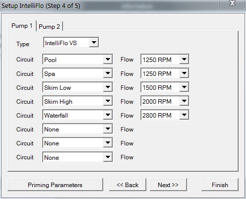
You do not schedule the "pump" you schedule "Circuits" and assign a speed to the Circuit. As an example.. My pool circuit is set to run at 1250 RPM
Here is a look at my speeds...
Set your Pool and Spa speeds to the lowest that you ever want to run. Then add more circuits to increase the speed.
The pump will always run at the faster of any two inputs.
Thanks,
Jim R.
The IntelliFlo always is wired direct to 240 VAC power.
The SWCG's power transformer MUST be wired to the load side of the pump/filter relay.
You do not schedule the "pump" you schedule "Circuits" and assign a speed to the Circuit. As an example.. My pool circuit is set to run at 1250 RPM
Here is a look at my speeds...
Set your Pool and Spa speeds to the lowest that you ever want to run. Then add more circuits to increase the speed.
The pump will always run at the faster of any two inputs.
Thanks,
Jim R.
When you refer to Circuits in the schedule, is that the same as assigning a schedule to the “Feature 1” circuit. So my pump running at 1200 rpm for 12 hours is on the Pool circuit and the hour at 2400 would be feature 1 circuit?
Rob,
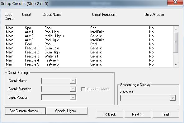
Look across the top of the pic below.. It shows what is a circuit, what is a circuit name and what is a circuit function..
The basic idea is to schedule "Pool" or "Spa" for the entire time you want the pump to run. As an example let's say 8 am until 8 pm.
Then add other circuits to control the speed.. Let's use Skim low from my set up.. As an example let's say 9 am until 10 am..
The pump will come on at 8 am and run at 1250 RPM until 9 am when Skim low comes on and the speed increases to 1500 RPM, until 10 am when Skim low shuts off and the speed goes back to 1250 RPM. Then at 8 pm the pump will shut off.. etc.
Feature circuits are what I use to control speeds and valves.
Thanks,
Jim R.
Ok great, thanks. This makes sense. Is it necessary to boost the rpm of the intelliflo while the polaris is cleaning, say for an hour. It has its own booster pump.
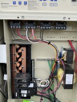
Also, should I move the white and yellow wires from the 2nd relay over to the Load 1/2 side of the 1st filter pump relay. Attached is the picture of how it’s currently wired when I had the single speed pump. I’ve already wired the intelliflo direct to the breaker. Thanks
Attachments
Rob,
The first thing you need to do is make sure which relay is the Pump/Filter relay. Based upon the wiring I can't tell for sure.
In theory, the top left relay should be the Pump/Filter relay.. You need to follow the two little wires at the top of the relay (coil wires) and make sure they are plugged into the pump/filter connection on the main board..
Tell me what your Aux 1 and Aux two relays control???
Thanks,
Jim R.
The far left relay is where the old single speed pump was connected, so I'm guessing it was the pump relay. I'll have to confirm when I get home but I think Aux 1 is the polaris booster pump and aux 2 is the pool lights (which are 12 volt and have a separate pentair transformer box)
Rob,
In theory, the only thing that should be running off of the pump's GFCI breaker is the IntelliFlo and the SWCG..
I suggest that you get another GFCI breaker for your booster pump.
That said, if you have not had any random trips of the main pump breaker, then you could just leave it like it is..
Electrically, the Yellow and White wires from the SWCG transformer only get power when the pump filter relay is closed, which is how it is now.. You could move them over to the load side of the pump/filter relay, but other than being where they should be, it won't make any electrical difference if you leave them where they are now..
Thanks,
Jim R.
So I just moved the Yellow/ White wires over to Load 1/2 side of the far left pump relay. It appears to be working fine, and no I haven't had any breaker tripping issues
Thread Status
Hello , This thread has been inactive for over 60 days. New postings here are unlikely to be seen or responded to by other members. For better visibility, consider Starting A New Thread.