Pad Plumbing Help

aaronleahy

Active member
Jul 22, 2018
39
Orlando, FL
Pool Size
7000
Surface
Plaster
Chlorine
Salt Water Generator
SWG Type
Pentair iChlor 30
Hello All,
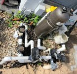
I thought I had a fairly good idea of my pad plumbing until I ran into an unexpected pipe yesterday while preparing to work in some new sheer features and switch over 2" pipe.

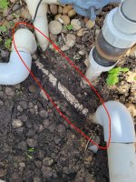
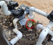
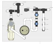
I have attached the flow diagram as I understood it - but I found this new pipe (in red) between my filter outlet and chlorinator inlet. I was completely sure that the filter went underground to my heater (25' away) and came back up at the chlorinator location. Those are the only spots where the plumbing goes below ground other than the suction (spa, skim, drain, cleaner) and return lines (pool, spa, soon-to-be sheers). I have 100% confirmed that the filter pipe is plumbed directly to the chlorinator pipe yet my heater is still getting water and heats the spa (although never as hot as I wanted and now perhaps this is why?) How is my heater getting flow? I can keep digging a bit, but this pad is super dense and soil is filled for almost a foot down with very compacted gravel.

Thanks in advance for any thoughts / help!
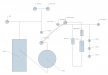
Pad.JPG
20210822_094508.jpg20210822_095624.jpg
 
Last edited:
The pic you posted does not show your heater or the heater in and out pipes.

The pic with the red circle - the pipe at the top of the circle leads to the chlorinator and returns. Where does the pipe at the lower right of the pic go to?
 
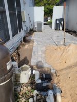
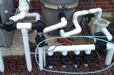
Please see picture with heater. It's a ways away so somewhat hard to show with the plumbing detail. I also added a new picture with the labeled pipes. The one in question is the one that bridges "to heat" and "from heat".

Thanks!

20210822_094437.jpg20210822_094427[1].jpg
 
Aaron,

I can tell you right now that sheer # 2 and #3 will have basically very little water flow.. if plumbed the way it is drawn.. :mrgreen:

Your heater will not work without water flow (actually pressure) so it should be obvious if the heater has no water flow.

It sure does not appear to me that the heater is in the loop at all. :scratch:

Edit.. I guess it could be set up so that only the water going to the spa is sent to the heater...

Thanks,

Jim R.
 
So TO HEAT runs to the heater inlet and FROM HEAT runs to the heater outlet.

Point to the pipe that is the red line on your drawing?
 
Aaron,

I can tell you right now that sheer # 2 and #3 will have basically very little water flow.. if plumbed the way it is drawn.. :mrgreen:

Your heater will not work without water flow (actually pressure) so it should be obvious if the heater has no water flow.

It sure does not appear to me that the heater is in the loop at all. :scratch:

Edit.. I guess it could be set up so that only the water going to the spa is sent to the heater...

Thanks,

Jim R.
Jim, Can you please help with the sheer descent plumbing plan? The pool company wanted to run a single 2" line from the pad to the 3 sheers with a ball valve at each for flow control but I requested they run 3 separate 1.5" lines back to the pad and I have planned 3 individual 2-way Jandy valves split off of a 2" manifold split from the pool return side. Set up like below. I'm totally open to a better way if this is not good.
InkedPool Manifold2_LI.jpg

As for the heater, I had the same thoughts. It does not appear to be plumbed at all, but definitely is. I first suspected it was possibly plumbed from the spa return to the heater and then to the spa jets like you said, but I *believe* I was able to get hot water out of the pool returns so that should rule that out. Unfortunately, the pool is drained in the middle of the remodel right now so can't confirm but I'm fairly sure.

My second thought is that pipe connecting what I labeled and thought to be "To Heat" and "From Heat" is actually some sort of weird bypass and that rather than being 90 elbows those are actually T's and continue down lower to the pipes that head to the heater. That would essentially mean that while some water goes from filter > heater > SWG, some of it would bypass the heater via that pipe and go directly from the filter to the SWG. This seems super weird but its literally the only thing I can think of at the moment. I don't know why they would have done this if it is in fact that way.
 
That would essentially mean that while some water goes from filter > heater > SWG, some of it would bypass the heater via that pipe and go directly from the filter to the SWG.

Where do you see evidence that the HEATER OUT pipe bypasses the heater and connects directly to the filter?

Looks to me that you have two pipes that run in parallel underground from HEATER IN and HEATER OUT to the heater.
 
Where do you see evidence that the HEATER OUT pipe bypasses the heater and connects directly to the filter?

Looks to me that you have two pipes that run in parallel underground from HEATER IN and HEATER OUT to the heater.

So the pipe labeled "to heat" was thought to go underground to the heater. The pipe labeled "from heat" was thought to come back from the heater. What is actually the case, is the the water exits the filter into the pipe labeled "to heat" goes 1' underground, then goes directly to the pipe labeled "from heat" via that short pipe shown by the red arrow. This then flows into the SWG and to the returns. Am I missing something? I don't see how this connects to the heater.
 
Last edited:

Enjoying this content?

Support TFP with a donation.

Give Support
So the pipe labeled "to heat" was thought to go underground to the heater. The pipe labeled "from heat" was thought to come back from the heater. What is actually the case, is the the water exists the filter into the pipe labeled "to heat" goes 1' underground, then goes directly to the pipe labeled "from heat" via that short pipe shown by the red arrow. This then flows into the SWG and to the returns. Am I missing something? I don't see how this connects to the heater.

OK, that is the way it looked to me but what through me for a loop was your labeling of TO and FROM HEAT.

I think you have to dig down a bit more and confirm there is nothing under that red pipe.

You can wait until the pool is operational to dig into this further. Or you can disconnect the unions at the heater IN and OUT and move the heater enough to be able to blow air or water into the lines and see if anything comes out around the equipment pad.

If you open up the Jandy pool/spa return valve whatever you blow into the heater out line should show there.
 
I'm totally open to a better way if this is not good.

AAron,

Your drawing looked like there was just one pipe going to sheer # 1, then #2, then #3...

Running a manifold with Jandy valves, like in your pic, is the way to do it.

I doubt that the underground pipe (red arrow) is a by-pass.. Since the pool is shut down, now is the time to take the pipes off the heater and see where they go.. Stick a garden hose in them and see where the water goes.

Thanks,

Jim R.
 
@Jimrahbe @ajw22 Thank you both for the water idea. I disconnected the heater unions and pushed a hose into the inlet and outlet. The inlet comes back to the check valve on spa side of the return plumbing and the outlet goes directly to the spa. This proves the heater is plumbed in just to the spa. This seems really bizarre to me but I guess does help with the overall system efficiency and head loss due to the water not frequently circulating through the heater during normal operation except for the spa spillover time (or using the spa which you'd need the heater for anyways). Is it worth re-plumbing the heater after the filter and before the chlorinator - assuming I can even get to those pipes? My only concern is the heater is now downstream of the SWG but I can't imagine its that big of a deal since its not a tab feeder or anything. I'm in Central Florida so haven't actually needed to heat the pool ever - just thought I could.

Inked20210824_081925_LI.jpg
Thanks!
 
Aaron,

Good job!! :thumleft:

I would leave is just like it is...

I suspect that the spa check valve is the kind that can't be rebuilt.. If that is true, then I would take this opportunity to replace it with a Jandy style check valve. I say this thinking that it is old and replacements are no longer available, which might not be true. :scratch:

Thanks,

Jim R.
 
Actually I paid someone who just installed that last year before I knew any better - and added a bunch of 1.5" pipe to my mostly 2" pad :(
I am going to replace it with a Jandy check valve. Since the heater is the last thing before the spa jets, should I put it on the heater outlet rather than in the location its currently at?

Also going to remove that piece of 1.5" pipe that goes through 5 elbows between the filter and SWG now that I know it doesn't go anywhere else. I can clean that up a lot.
 
Aaron,

I assume you have a spillover spa.. If that is true, that check valve is there to prevent the spa water from drain backwards into the pool through the Return valve.

Seems to me you could put that valve anywhere between the spa jets and where it is now. Just keep in mind that you will need to be able repair or replace it later.

You may not have that issue due to the height of your heater connections. :scratch:

Why did you have the original valve replaced.


Thanks,

Jim R.
 
I agree the heater connection height should suffice but I definitely want the check valve all the same.
He replaced it because the old one of the same type was making a ton of noise when water was going through it. He added all the 1.5" pipe to plumb in the chlorinator.

I'm in the process of replacing the 3 inlet diverter valves as well since even though all my suction lines are 2" (except cleaner), the lines between the diverters before the pump reduce down to 1.5". I'm trying to get as much flow as possible for the new sheer descents, reduce noise, and increase efficiency so hence removing all the 1.5" prior to the pool / spa returns.

Edit - I'm planning 2 check valves total. One for the spa returns either at the heater or in the location of the current spring check valve, and one between the filter & SWG mainly to install my Flowvis.
 
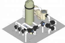
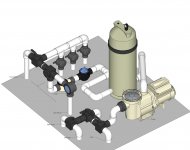
Could you please take a look at my proposed new plumbing layout and see if anything seems amiss? I do know everything is a little tight, but my pad is very small and right at where my patio and screen enclosure meet - so not much room.
The suction plumbing from the drain/skimmer/cleaner/spa is basically staying the same as how it is currently but I'm replacing the 3 current Jandy grey diverters with new 2" diverters with 2" piping between them since they are currently plumbed for 1.5" and that's the most constricted part of entire system. Once that is complete it will be 2" all the way until the pool / spa / sheer returns.

Thanks!

PlumbingTop.jpgPlumbingLeftIso.jpgPlumbingRightIso.jpg
 
Thread Status
Hello , This thread has been inactive for over 60 days. New postings here are unlikely to be seen or responded to by other members. For better visibility, consider Starting A New Thread.