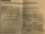
My mechanical timer for pool pump stopped working so decided to take the plunge and go modern with WiFi models (from Amazon).
Amazon Link: DEWENWILS Outdoor Smart Wi-Fi Outlet Box, Heavy Duty 40A 120-277 VAC 2HP Wireless Controller Timer Switch for Pool Water Heater SPA, Compatible with Smart Phone, Alexa, Google Assistant, UL Listed: Amazon.com: Industrial & Scientific
Manufacturer link: Outdoor Smart Wi-Fi Outlet Box
I've got two of them: one for pool pump and one for the Polaris booster pump. I've got them wired independently at this time (each connected to 240VAC) and they are working great (as independent timers). Wife loves being able to remotely turn off loud pumps when enjoying the pool area!
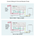
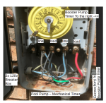
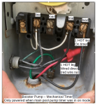
My problem is this - the two previous mechanical timers were wired such that the booster pump would ONLY operate/run when the main pool pump was engaged/on (main pool pump timer was on). I would like to wire these WiFi controllers the same but cannot figure out how to make that work. I will attach some pictures of the old wiring - it appears that the Booster timer had one hot leg hard wired and the other controlled by the timer with the controlled line being supplied by the main pool pump switched line. So if I'm interpreting it correctly only one of the HOT legs on the booster pump was controlled by the timer and would only engage when it had power being supplied from the pool pump load side.
Any suggestions on how to wire? Should I follow the same setup as was with the mechanical timers?
Amazon Link: DEWENWILS Outdoor Smart Wi-Fi Outlet Box, Heavy Duty 40A 120-277 VAC 2HP Wireless Controller Timer Switch for Pool Water Heater SPA, Compatible with Smart Phone, Alexa, Google Assistant, UL Listed: Amazon.com: Industrial & Scientific
Manufacturer link: Outdoor Smart Wi-Fi Outlet Box
I've got two of them: one for pool pump and one for the Polaris booster pump. I've got them wired independently at this time (each connected to 240VAC) and they are working great (as independent timers). Wife loves being able to remotely turn off loud pumps when enjoying the pool area!
My problem is this - the two previous mechanical timers were wired such that the booster pump would ONLY operate/run when the main pool pump was engaged/on (main pool pump timer was on). I would like to wire these WiFi controllers the same but cannot figure out how to make that work. I will attach some pictures of the old wiring - it appears that the Booster timer had one hot leg hard wired and the other controlled by the timer with the controlled line being supplied by the main pool pump switched line. So if I'm interpreting it correctly only one of the HOT legs on the booster pump was controlled by the timer and would only engage when it had power being supplied from the pool pump load side.
Any suggestions on how to wire? Should I follow the same setup as was with the mechanical timers?