New Model Pentair MasterTemp Heater

ajw22

TFP Expert
Gold Supporter
Silver Supporter
Bronze Supporter
TFP Guide
Jul 21, 2013
52,891
Northern NJ
Pool Size
35000
Surface
Plaster
Chlorine
Salt Water Generator
SWG Type
Pentair Intellichlor IC-60
@Jimrahbe @JamesW have you seen that Pentair has a new model MasterTemp heater according to the Installation manual Rev P 8/2020 currently on their website? It looks like Pentair again made significant changes to the model and kept the same name and SKU.

It looks like the manual has been significantly rewritten. And unfortunately the manual for the MasterTemp that most customers currently have is not on the MasterTemp page.

New manual is at https://www.pentair.com/content/dam...stertemp/Manual-MasterTemp-472592-English.pdf

Interesting changes seem to be....
  • Display is now 2 lines and shows error codes - page 46
  • No SERVICE HEATER or SERVICE SYSTEM LED
  • The diagnostic LEDs are not on the back of the board.
  • Page 45 shows the Fenwal module and it is different with 5 possible error states instead of 3.
 
  • Like
Reactions: JoyfulNoise
@Jimrahbe @JamesW have you seen that Pentair has a new model MasterTemp heater according to the Installation manual Rev P 8/2020 currently on their website? It looks like Pentair again made significant changes to the model and kept the same name and SKU.

It looks like the manual has been significantly rewritten. And unfortunately the manual for the MasterTemp that most customers currently have is not on the MasterTemp page.

New manual is at https://www.pentair.com/content/dam...stertemp/Manual-MasterTemp-472592-English.pdf

Interesting changes seem to be....
  • Display is now 2 lines and shows error codes - page 46
  • No SERVICE HEATER or SERVICE SYSTEM LED
  • The diagnostic LEDs are not on the back of the board.
  • Page 45 shows the Fenwal module and it is different with 5 possible error states instead of 3.
It also looks like there is some new built-in feature allowing you to connect an IntelliValve to the heater for automatic by-pass control from the heater.. Still looking for more documentations on how to wire it inside the heater and the configuration on the heater panel...

BP-VALVE (By-pass Valve): Enabled/Disabled

By-pass Valve Description
The purpose of the automatic BPVALVE (bypass valve) feature is to by-pass the flow of water from the heater
inlet to the heater outlet when the heater is not firing. There is a minimal amount of water flow through the
heater when the heater is not firing, and a maximum water flow through the heater when the heater is firing.
For more information about Manual By-Pass and Automatic By-Pass valves, see page 14-15.

By-Pass Enabled
When the BYPASS VALVE feature is enabled and there is a call for heat, the by-pass valve closes to allow
water to flow through the heater. It takes 30 seconds for the bypass valve to rotate to the closed position. This allows
the valve to complete rotation so there is sufficient water flow and pressure to prevent the water pressure switch from
trigging an error. When the call for heat ends, the water flow continues through the heat exchanger for a cool down
period of one minute. After the cool down period, the by-pass valve will rotate so that water no longer flows through
the heater.

By-Pass Disabled
When the BYPASS VALVE feature is disabled, there is no automatic switching of the by-pass valve when the heater
starts a heating cycle. The valve stays in the position and water always flows through the heater.
 
  • Like
Reactions: tomas21
Excellent so this will be one intellivalve not specifically controlled by the IntelliCenter but instead by the heater when called upon.... when heating valve will direct water through heater... when not heating valve will bypass heater.
 
By-Pass Enabled
When the BYPASS VALVE feature is enabled and there is a call for heat, the by-pass valve closes to allow
water to flow through the heater. It takes 30 seconds for the bypass valve to rotate to the closed position. This allows
the valve to complete rotation so there is sufficient water flow and pressure to prevent the water pressure switch from
trigging an error. When the call for heat ends, the water flow continues through the heat exchanger for a cool down
period of one minute. After the cool down period, the by-pass valve will rotate so that water no longer flows through
the heater.

I updated my heater to the new board and ignition control switch (Fenwal). When using the on board heater bypass, and communicating with the IC, the valve will not ever return to the bypass position. The heater stays in the cool down period mentioned above. Only when communicating with the IC though. If I disconnect the RS-485 and run the heater standalone, it functions just fine. Cool down period runs for 1 minute, and the valve returns to the bypass position.

If you connect yours like that, would be curious to know if yours will do that.

I moved the valve back to my IC board and used the internal Heater circuit to control the valve any time the heater is engaged. Having the bypass valve on the heater board would be important if that was going to be the one valve that pushed me over the limit. I already have the valve expansion module and I only have 7 valves with the heater bypass, so I am ok.

Having any heater errors on the IC is nice. You don't have to stand upside down and look at the LED's on the control board to see what's happening.

--Jeff
 
I’m guessing this is the “slow nudge” to get everyone to migrate to the IntelliCenter. Is it backwards compatible with an old EasyTouch panel? I’m guessing not. I see a really, really expensive equipment pad upgrade in my future … hopefully I can sell the house before that is necessary 😬

Calling @MyAZPool for his thoughts …
 
It still works with the contact closure for a fireman's switch. No need for the comms unless you have that capability.

--Jeff
 
So I have the newer model heater and ample valve ports on the ic expansion module. What is the ideal configuration with this heater?
 
I don't think it really matters. If my heater board would exit the cool down mode, I would likely wire my bypass directly to the heater board. But since it won't, I will keep the valve wired to the IC.

Would be curious to know if your heater ever exits the cool down mode. You don't need to have the bypass wired up to the heater to determine this. After you have run the heater, and turned it off, press any button on the heater membrane pad to bring up the display on the heater. Display will indicate whether in cool down mode, I think on the bottom line of the display, if I remember right.

I just ordered a replacement heater board. Mine took a hit from lightning. I can advise if the new board fixes my issue with the cool down mode, once I get it in and installed.

--Jeff
 

Enjoying this content?

Support TFP with a donation.

Give Support
I’m guessing this is the “slow nudge” to get everyone to migrate to the IntelliCenter. Is it backwards compatible with an old EasyTouch panel? I’m guessing not. I see a really, really expensive equipment pad upgrade in my future … hopefully I can sell the house before that is necessary 😬

Calling @MyAZPool for his thoughts …
Matt...
This topic came up back in June.
When I questioned the IntelliCenter Product Manager about it, he referred me over to the Heater Group Product Manager.
He was very helpful and provided the following information to me which I posted here...
r.
 
  • Like
Reactions: JoyfulNoise
I updated my heater to the new board and ignition control switch (Fenwal). When using the on board heater bypass, and communicating with the IC, the valve will not ever return to the bypass position. The heater stays in the cool down period mentioned above. Only when communicating with the IC though. If I disconnect the RS-485 and run the heater standalone, it functions just fine. Cool down period runs for 1 minute, and the valve returns to the bypass position.

If you connect yours like that, would be curious to know if yours will do that.

I moved the valve back to my IC board and used the internal Heater circuit to control the valve any time the heater is engaged. Having the bypass valve on the heater board would be important if that was going to be the one valve that pushed me over the limit. I already have the valve expansion module and I only have 7 valves with the heater bypass, so I am ok.

Having any heater errors on the IC is nice. You don't have to stand upside down and look at the LED's on the control board to see what's happening.

--Jeff
So let me get this straight..

  • Option 1 - If you hook the intellivalve to the heater board... and run the RS-485 to the IC... your heater never comes out of cool down mode?
  • Option 2 - If you hook the intellivalve to the heater board... and run the standard firewall 2 wire... your heater will come out of cool down mode but you would loose added features like error communicating to the IC?
  • Option 3 - If you hook the intellivalve to the IC expansion board, run the RS-485 to the IC from heater ... everything works fine and you get new features like error codes to the IC? (this is the option you stuck with since 1 didn't work and you didn't want 2 so you could get more communations back to IC?
 
  • Like
Reactions: MyAZPool
  • Option 1 - If you hook the intellivalve to the heater board... and run the RS-485 to the IC... your heater never comes out of cool down mode?
That is correct. When I ran the heater in a standalone mode, meaning jumpered the fireman's switch connection and disconnected the RS-485 connection at the heater, and only controlled via the heater keypad, the bypass worked as expected. Heater fired up, allowed 30 seconds for the valve to change positions, and when turned off, stayed in cool down mode for 1 minute, and then returned the valve to the bypass position.
  • Option 2 - If you hook the intellivalve to the heater board... and run the standard firewall 2 wire... your heater will come out of cool down mode but you would loose added features like error communicating to the IC?
I never tried this. Not sure that this would be capable of running the heater bypass as intended. Running just the 2 wire to the fireman's switch will kill power to the heater unless there is a call for heat. Since the power for the valve actuator is derived from the heater control board, I am not sure the actuator would remain powered up at that point to revert to the bypass setting.
  • Option 3 - If you hook the intellivalve to the IC expansion board, run the RS-485 to the IC from heater ... everything works fine and you get new features like error codes to the IC? (this is the option you stuck with since 1 didn't work and you didn't want 2 so you could get more communations back to IC?
That is correct. Program the valve actuator to act on the imbedded heater circuit in the IC. It will actuate when there is a call for heat. If the heater reaches setpoint, I believe the valve will return to the bypass position, until heat is called for again. It has been a while since I watched this happen. And currently my board is toast so I'm waiting on a replacement, otherwise I would go verify.

IIRC, if you only have the 2 wire fireman's switch wired up, I believe there is no selection for MasterTemp Heater, only a Gas Heater. When you connect the RS-485 to the IC, the IC can see the heater and then there is a selection available for the MasterTemp.

--Jeff
 
Thanks.. So sounds like I need to stop using the fireman, run RS-485 from heater to IC, and I will try to use the onboard bypass valve connection on heater to see how things work out.
 
I would for sure run the RS-485 at a minimum. It is really nice to see the heater error on the IC or your phone. I cut the gas supply once and then kept the bypass closed on another just so I could get a few errors to see what it was like.

--Jeff
 
Awesome.. I am going to reconfigure our setup so the heater uses the 3 wire setup (change configuration from 2 wire) and use the heater onboard bypass valve to control an intellivalve.. .will test to make sure works especially after cool down
 
I am going to reconfigure our setup so the heater uses the 3 wire setup (change configuration from 2 wire) and use the heater onboard bypass valve to control an intellivalve.. .will test to make sure works especially after cool down
The 3 Wire (3W) is not the same thing as the RS485 port.

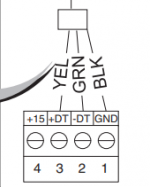
The RS485 port is a 4 wire port, which uses red, yellow, green and black.

Red is the power, black is ground, yellow and green are data.

The only time you need the red and black is to power a remote device like a Spa Side Remote.

Things that have their own power, like a SWG or heater only use the yellow and green data cables.

This also says to use the black ground, but I don't think that it is necessary.

1635720387688.png
1635720725173.png
 
Last edited:
The 3 wire setup is different from the RS-485. You don't need to do the 3 wire setup.

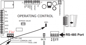
Just need to wire the RS-485 connector to the 485 port on the lower right of this diagram to the 485 bus on the IC. Any of the 485 terminals in the IC will be fine.

1635720388144.png

The 3 wire connection is the connector on the lower left. Do not need to connect anything there and no jumpers to move.

Really only need to connect the GRN/YEL connectors. Although Black may be necessary if there is noise. I noticed no difference between BLK/GRN/YEL and just GRN/YEL connected.

--Jeff

EDIT - James beat me to it!
 
The 3 wire setup is different from the RS-485. You don't need to do the 3 wire setup.

Just need to wire the RS-485 connector to the 485 port on the lower right of this diagram to the 485 bus on the IC. Any of the 485 terminals in the IC will be fine.

View attachment 380380

The 3 wire connection is the connector on the lower left. Do not need to connect anything there and no jumpers to move.

Really only need to connect the GRN/YEL connectors. Although Black may be necessary if there is noise. I noticed no difference between BLK/GRN/YEL and just GRN/YEL connected.

--Jeff

EDIT - James beat me to it!
Ok.. So the 2-wire fireman will stay as is and I will add the additional RS-485 wiring on the heater control panel to the IC expansion module that has open com port.

Or the 2-wire fireman is not longer necessary and all comes are through RS-485?
 

Enjoying this content?

Support TFP with a donation.

Give Support
Thread Status
Hello , This thread has been inactive for over 60 days. New postings here are unlikely to be seen or responded to by other members. For better visibility, consider Starting A New Thread.