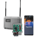
New install of jandy TCX won't turn on out the box

tylersnag

In The Industry
Mar 22, 2025
15
Chattanooga, TN
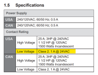
My electrician friend installed a jandy tcx for one of our customers so he can have an automated system. Anyway, we turn it on and the electrician said he saw the light. But when I tried to connect to it from the app no lights were on. I tried to reset with turning the breaker off and holding the two buttons and what not. But that did nothing. We tested the PIB and it was getting the correct voltage. It was set to the correct voltage. The fuse on the front. Underneath the 110/220 switch was good. We didn't test the transformer bc neither of us knew what the transformer was dropping it down to for us to confirm whether it was working or not. Right now he only has the single speed pump connected to the TCX. The lights work on their own. But for some reason the control hub is not receiving any power what do ever.

Jandy is closed and I want to try and potentially seek help to fix it this weekend. Does anyone have any advice?


Last edited:
Update 2:
I finally connected with technical support at Fluidra / Jandy. Yes there is a factory default reset sequence for the Jandy TCX. And yes, this partially fixed my issues. More about the partially later.

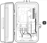
The Jandy TCX consists of the TCX PIB (Power Interface Board) which contains the relay, 2 RS-485 4 wire terminal blocks, and a plug in for a JVA. The second part of the TCX is the Command Hub which contains the Wi-Fi or wired ethernet, and bluetooth, connectivity plus three buttons for manual control of the TCX at the unit. All other control is done with the iAqualink mobile device app.

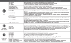
On the Command Hub is a button referred to as 'Service' (not labeled as such) which toggles between Auto, Quick Clean, Service, Time Out. The second button is to manually turn on/off the Pool Pump. The third button is for pairing a bluetooth device.

Now for the Reset to Factory Default sequence:
1. Power off the TCX, as a precaution wait 30 seconds.
2. Press and hold both the Service and Pool Pump buttons, while
3. Power on the TCX.
4. Look for the service lights to blink wildly.
5. I waited for 30 seconds after power on while still holding the 2 buttons (this part of the instructions was not clear, but worked for me. Then power off. Release buttons. (not sure you had to hold the buttons for the entire time after the blinking wildly, but this worked for me.
6. Wait 30 seconds after power off.
7. I did not always have a good reset so I adopted the following. Repeat steps 2-6 a second time.
8. Power up the TCX with no RS-485 devices connected except for the Command Hub. Power on for at least 30 seconds.
9. Power off the TCX.
10. Wait 30 seconds after power off.
11. Now proceed with connectivity of the TCX as provided in the Installation and Operations Manual.
12. Power off the TCX and wait 30 seconds after power off.
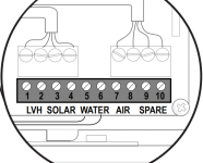
13. Connect any RS-485 connected devices. Beware that RS-485 devices will only register with the TCX when they are powered on either by the TCX relay or otherwise.

Good luck!

It appears that my brand new Century VGreen EVO VSP RS-485 communications may now be toast and I will be troubleshooting this. The salt water chlorine generator is communicating and can be controlled from iAqualink. The VSP pump is operating in standalone mode.

We didn't test the transformer bc neither of us knew what the transformer was dropping it down to for us to confirm whether it was working or not.
1742667674842.png
 
Thank you. Loads of info to go off of here.

I didn't think to take photos when I was there this morning bc I was in a hurry

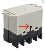
But in this photo, it's yours I took a screenshot and circled the top left. That item on ours doesn't look like that it looks like the molding is raised. I wouldn't say burnt. But it def doesn't look like this in the photo. I'll try and get photos tomorrow and run through these videos you sent so I can see what needs to be done 1000002466.png
 
  • Like
Reactions: JamesW
The transformer should output 24 VAC.

The power to the relay is usually 24 VDC.

The relay should show the coil voltage labeled on the side.

The communication wires are 10 VDC from red to green.

1742668496817.png

The power center supplies the controller 10 VDC via the two (2) outside wires (red and green) of the four (4)
conductor cables.

If the voltage drops below 8 VDC, the display will flicker on and off.

The two (2) inner wires (yellow and black) provide the two-way communication link between the controller and the power center.

They communicate via serial communication, using signals like the standard "RS-485".

G7L-2A-BUBJ-CB-IN DC24

G7L-2A-BUBJ-CB DC24


1742668755128.png
 
Last edited:
We tested the PIB and it was getting the correct voltage. It was set to the correct voltage.
Is the power 120 or 240 volts?

Is the input power connected to terminals 1 and 3?

Terminals 1 and 3 are the "Line" terminals.

Terminals 2 and 4 are the Load Terminals.

When the relay coil gets 24 VDC, the contacts close 1 to 2 and 3 to 4.

The circuit board is powered from the relay Line Terminals.
1742671935679.png

1742671142014.png


1742671291927.png

1742671413505.png

The relay has a test button.

If you press the test button, the relay closes.

1742672202767.png
1742672515684.png
 

Enjoying this content?

Support TFP with a donation.

Give Support
The Command Hub gets power from the RS485 wires and you should measure 10 VDC from Red to Green.

Verify 10 VDC.


Make sure that the wire colors on both sides are in the correct order.

1742674349677.png

1742674531042.png

1742674656325.png

1742674702530.png

1742674956490.png

1742674964933.png
 

Attachments

  • 1742675003183.png
    1742675003183.png
    2.4 MB · Views: 1
Last edited:
Is the power 120 or 240 volts?

Is the input power connected to terminals 1 and 3?

Terminals 1 and 3 are the "Line" terminals.

Terminals 2 and 4 are the Load Terminals.

When the relay coil gets 24 VDC, the contacts close 1 to 2 and 3 to 4.

The circuit board is powered from the relay Line Terminals.
View attachment 633691

View attachment 633686


View attachment 633687

View attachment 633688

The relay has a test button.

If you press the test button, the relay closes.

View attachment 633692
View attachment 633698
Voltage is 230, set to 230 on the PIB and the loads are in 2 and 4.

I'm going to try and go back tomorrow during the day to take a look at it.
 
  • Like
Reactions: JamesW
Verify 10 VDC at the Command Hub (Red to Green).

Verify 240 volts from Terminal 1 to Terminal 3 on the relay.

The board has two wires that go to those terminals to power the board.

1742738944753.png

1742739311489.png
 
Waiting on electrician to arrive to wire the pump back up to it for me. But this is what mine looks like. The rs485 inside the pub of mine is connected at the bottom instead of of the top like yours. Does that make a difference, and notice top right. My mov1 black piece looks melted but idk if that matters. It's just the plastic that is. Circuit board looks fine

Hard to tell but the rbyg cables are in the correct position
1000002473.jpg
 

Attachments

  • PXL_20250323_155942630.jpg
    PXL_20250323_155942630.jpg
    322.6 KB · Views: 5
That fried MOV1 is why you have no power.

MOVs or metal oxide varistors are devices designed for controlling mains switch ON surges in electrical and electronic circuits. Metal oxide varistors, or simply varistors, are non-linear surge suppressor devices used to suppress sudden, high abnormal voltage transients or surges, especially during power switch ON or thunder lightning situations.

MOVs are primarily used in sensitive electronic circuits to safeguard against catastrophic failures.

Did someone power it up with 230V while that slide voltage switch was set to 115V?

Where did you get that unit from?
 
Last edited:

Enjoying this content?

Support TFP with a donation.

Give Support