New Construction Started - Willis, TX (north of Houston)

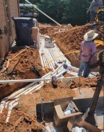
Barring any delays, plumbing is scheduled for today and I'm reviewing the plan.

Unless the pump is below the water level or more than 2 feet above the water, I would not use a valve.
Of course there was a delay but they're onsite now and digging trenches.

On the subject of check valves, the PB is advising an anti corrosive check valve is required between the heater and the salt cell. I've also been advised Jandy's largest size is 2". I'm working on getting the PN and investigating.

1657733802765.png
 
@JamesW
Although I was able to find them locally, the plumber's supplier could not supply 4" sweep elbows and they are recommending 45's in lieu of sweeps. I don't think that's unacceptable but am curious if there's a specific distance they need to be from one another? In other words is it not a good idea to have them back to back and better to have a length of pipe (of a certain length) between them to maximize flow?
 
Each 90 is "equivalent" to 10 feet of straight pipe.

Each sweep 90 is equivalent to 5 feet of straight pipe.

If you used (10) regular 90s, that's equivalent to adding 100 feet of pipe.

If you used (10) sweep 90s, that's equivalent to adding 50 feet of pipe.

So, the difference is equivalent to 50 feet of pipe.

At 200GPM, the velocity is 5.1 feet per second and the head loss is 2.1 feet per 100 feet of pipe.

So, the head loss difference is only 1 foot of head at 200 GPM, which is not a big deal.

Hopefully, the line can be run with fewer than (10) 90s.

In any case, this is the type of reason it pays to use the bigger pipe and avoid problems.


1657735199592.png

1657735114815.png
 
Update, the valve is actually made by Magic Plastics and touts corrosion resistant features. It's only available in 2".


1657738091436.png
 
It looks like I'll need to go from 2.5" to 2" on the heater discharge. I assume the IC60 is a 2" connection anyway?

1657738352857.pngIt
 

Enjoying this content?

Support TFP with a donation.

Give Support
Last edited:
Regarding the IC60, the manual advises a 3" distance from the heater outlet?
The heater should have a cooldown period after meeting the call for heat, so the cell should never be exposed to excessive heat even if it were closer than 3 feet.

However, it's usually best to follow the recommendations to avoid any warranty issues.

Even if a problem was not caused by being closer than 3 feet, Pentair could still use it as a reason to deny coverage for an issue.
 
If you go with the smaller Magic Plastics check valve, I would move it to after the heater and before the 5 psi check valve bypass.
Why the differentiation between the Jandy & Magic Plastics CV in terms of the location? Inlet/outlet size?
 
Why the differentiation between the Jandy & Magic Plastics CV in terms of the location? Inlet/outlet size?
Correct, the Jandy is bigger and can take the full flow.

By moving the check valve, it only gets the heater flow and not the bypass flow.

If you can get the 2 x 2.5" Magic Plastics CR2, then that can probably go either place with the outside 2.5" fittings.

The site says that it comes in 2.5".

I can't find the rated flow for the CR2.


1657743768063.png
 
Last edited:
I don't think that Pentair would object to their own check valve being used as the required check valve.

In any case, the Magic Plastics check valve with 2.5" fittings will probably not create too much head loss.

If you can find the rated flow and head loss chart for the Magic Plastics valve, that would be helpful.

In any case, it's on the builder if there is a problem with the product they choose.
 
Below is what the manual says.

Install the chemical feeder downstream of the heater.

Install a chemical resistant one-way check valve between the heater and the chemical feeder to prevent back-siphoning through the heater when the pump is off.

Exercise care when installing chemical feeders so as to not allow back siphoning of chemical into the heater, filters or pump.

When chemical feeders are installed in the circulation of the piping system, make sure the feeder outlet line is down stream of the heater, and is equipped with a positive seal noncorrosive “Check Valve”, (P/N R172288), between the feeder and heater.

Install a corrosion resistant positive seal “Check Valve”, (P/N R172288), between the heater and the chlorinator to prevent concentrated chemicals from back-siphoning into the heater.

Back-siphoning is most likely to occur when the pump stops, creating a pressure-suction differential.

Do NOT sanitize the pool by putting chlorine tablets or sticks into the skimmer(s). When the pump is off, this will cause a high concentration of chlorine to enter the heater, which could cause corrosion damage to the heat exchanger.


In my opinion, the check valve requirement only applies to a tab feeder and not to a SWG.

In any case, I suspect that Pentair would not object to their 2.5 x 3” check valve being used for the purpose.

The check valve (P/N R172288) actually specified is shown below, but it is a 2 psi check valve that would create too much head loss and it would reduce the flow through the heater too much unless you increased the bypass check valve strength by 2 psi to compensate from 5 psi to 7 psi.

If you put the Magic Plastics CR2 after the heater and before the T for the bypass check valve line, then the check valve should not get more than 60 GPM, which should be fine.

Also, if Pentair really was worried about the SWG creating an issue due to chlorine gas or hydrogen gas, they could program in a “Cool Down” period of about 10 minutes where the SWG would turn off about 10 minutes before the pump was scheduled to turn off, which would allow any residual chlorine or hydrogen gas to be cleared out.


1657829155123.png
 
  • Like
Reactions: Duffatola
Construction updates:
Catching up, the long plumb was done over two days 7/13-7/14. Phase 2 (pad work) will be completed at a later date. The first phase of electrical work was done on 7/19. We've been in a holding pattern since due to needing the Aerobic septic system repaired before covering the trenches because septic system irrigation piping will have to be routed in them. This has been a painful learning process. I was under the impression that I, personally, would simply run new purple pvc lines to new spray heads and be done with it. After contacting the septic system maintenance company to advise, I was told the complete system had to be engineered by an environmental engineer and then submitted for permitting. I was also advised a licensed contractor had to do the work. There are also rules with regards to how close spray heads can be in proximity to the pool, property easements, etc.. I just received the new plan/layout today (and a $850.00 bill) from the engineer and now am awaiting to hear back from the several contractors I contacted to bid on the install. These are additional costs I certainly didn't see coming.
On the pool build side, we can't find the IntelliFlo XF VSF pumps (ordered two months ago) and as mentioned won't be able to start tile and coping until the septic system work is completed.

Here are the latest images. Unfortunately due to my drone being out of commission until recently, I had to go old school to take the photos...
 

Attachments

  • East Side.jpg
    East Side.jpg
    200.3 KB · Views: 34
  • Electrical Stub Outs.jpg
    Electrical Stub Outs.jpg
    353.6 KB · Views: 35
  • Equipment Pad - Filter-Water Feature Piping.jpg
    Equipment Pad - Filter-Water Feature Piping.jpg
    325.2 KB · Views: 35
  • Equipment Pad - Infinity Edge Piping.jpg
    Equipment Pad - Infinity Edge Piping.jpg
    295.5 KB · Views: 34
  • North Side.jpg
    North Side.jpg
    265.5 KB · Views: 34
  • South East Side.jpg
    South East Side.jpg
    400.4 KB · Views: 34
  • South Side.jpg
    South Side.jpg
    309.1 KB · Views: 34
  • South West Side.jpg
    South West Side.jpg
    272.7 KB · Views: 33
  • To Equipment Pad.jpg
    To Equipment Pad.jpg
    248.2 KB · Views: 33
  • West Side.jpg
    West Side.jpg
    257.9 KB · Views: 34

Enjoying this content?

Support TFP with a donation.

Give Support
Thread Status
Hello , This thread has been inactive for over 60 days. New postings here are unlikely to be seen or responded to by other members. For better visibility, consider Starting A New Thread.