New Construction Started - Willis, TX (north of Houston)

Per PB: It is recommended by ANSI/APSP 7 Standards for Suction Entrapment Avoidance –that residential pools water velocity not exceed 8 ft per second.
That standard does not actually set the velocities.

It refers the issue to ANSI/APSP/ICC-5 2011, which does say 8 feet per second.

8 feet per second is 184 GPM in 3" pipe..

Assuming a total equivalent length of 120 feet, the velocity at 180 GPM is 7.95 feet per second and the head loss is 8.98 feet.

180 GPM should give you good action on the sheers and the infinity edge.

1655819047495.png


1655818531208.png
1655818420593.png
ANSI/PHTA/ICC-7 2020 American National Standard for Suction Entrapment Avoidance in Swimming Pools..

Published on Apr 19, 2021

The purpose of this standard is to establish anti-entrapment performance requirements for public and residential swimming pools, wading pools, field-constructed spas and hot tubs, and any other bather-accessible body of water, including but not limited to, catch pools, infinity edge basins, and water features that contain a skimmer, fully submerged Suction Outlet Fitting Assembly (SOFA) or vacuum port fitting.

 
  • Like
Reactions: Duffatola
Ok, 3" will probably be ok.
So, most likely, the pump will be able to get to full speed without cavitating.

you would need to know the Net Positive Suction Head Required for the IntelliFlo XF at full flow.
In other words, there is risk, although slight, 3" may underperform and possibly cavitate. However using 4" will provide maximum performance with no cavitation concerns?
 
In other words, there is risk, although slight, 3" may underperform and possibly cavitate. However using 4" will provide maximum performance with no cavitation concerns?
Yes.

Calculating exactly where cavitation will occur is difficult.

Besides the conversion of water to vapor, you also have dissolved gasses in the water that begin to come out earlier than water vapor.

With the infinity edge, the water will get a lot of air mixed in and dissolved and that can begin to come out of solution at lower pressure creating a type of cavitation.

You also get areas of lower pressure around fittings, edges, turns etc. which can create areas of low pressure especially at higher water velocities.
 
Last edited:
Here is a different video explaining cavitation.

I don't know the pipe size, but it looks like maybe 3" pipe.

At 120 GPM they indicate bubbles, which seems like it would not happen at 120 GPM at 3", but the tank is also getting a lot of air mixed in the water, which is what I think that the bubbles probably are.

At full speed, they are getting 150 GPM and a lot of cavitation.

I don't think that it is vapor cavitation.

It's probably dissolved gasses cavitation, but it still affects the pump and the performance.

1655822035881.png
1655822294856.png


Last edited:
In other words, there is risk, although slight, 3" may underperform and possibly cavitate. However using 4" will provide maximum performance with no cavitation concerns?
And in your opinion, this is the case regardless whether it's the infinity edge pump or the water feature pump?
 
Shifting gears to valve sizing. Jandy makes valves that can accommodate a size range within 1/2". If I need a 2-port 2" valve (2" pipe fit on each end), I can opt for a 1.5"-2" or a 2"-2.5". Would you recommend the latter for better flow?
 
Shifting gears to valve sizing. Jandy makes valves that can accommodate a size range within 1/2". If I need a 2-port 2" valve (2" pipe fit on each end), I can opt for a 1.5"-2" or a 2"-2.5". Would you recommend the latter for better flow?
Yes.

For the larger pipe, like in front of the infinity pump, you can use a 2.5" x 3" 2 port valve.
1655825496423.png
 

Enjoying this content?

Support TFP with a donation.

Give Support
Maybe check with Pentair and ask them what spring strength should be used if you were going to do a spring bypass on the Mastertemp.

You don't have to do a spring bypass on the Mastertemp as the flow will not exceed 120 GPM as specified in the manual.

However, in my opinion, putting anything over 60 GPM is unnecessary and it can create extra wear on the heater components.
I have contacted Pentair though their tech support phone number (wait time was 49 minutes so I left a call back number) as well as through tech support contact/email to inquire about the spring rating on a check valve. I've not received a response but I did find this in their Questions/Answers regarding their heaters:

1655845300259.png

This attachment is the kit but the CV is not spring loaded.
 

Attachments

  • Pentair Bypass Kit - 462048.pdf
    40.8 KB · Views: 3
That's for automatically bypassing the heater when the heater is not in use.


1655845984497.png

That's a good idea, but the check valve bypass is in addition to the automatic bypass.

The design of the check valve bypass is to use a spring check valve with the right force to open only once the heater has enough flow and to bypass additional flow around the heater.
 
  • Like
Reactions: Duffatola
That's a good idea, but the check valve bypass is in addition to the automatic bypass.
Here is the latest version of the filter piping plan. The PB is requesting pipe sizes and valve types and counts (I told them I'd spec all the valves) for all three systems. A couple of items are TBD (Flow Switch and Spring CV). One thing that I'm curious about is the placement of the CV between the pump and the filter. Is there a reason it's not downstream of the filter before the 3 port valve? It seems to me protecting a backflow into the filter would be a good idea.

1655847911119.png
 
The 3 pool suction valves should be 4716, not 4718.

I would leave the check valve between the pump and filter.

The 3-way after the filter should be Pentair 263056 with an intellivalve so that you get the automatic bypass.

Actually, I would do all Pentair valves if you are going to use Pentair actuators as the screws are different threads.

Also, I am not sure that a large 2.5 x 3 jandy neverlube will take an actuator.

The Pentair valves say actuator compatible.

1655851452351.png

The threeway after the cell should be 4719, not 4718.

You should put a 7307 check valve on the spa jet line for spillover mode.

1655850907170.png

1655850589016.png

 
To mount an actuator, you have to remove 4 screws and install 4 longer screws.

The problem with using a valve actuator from one brand and a valve from a different brand is that the screws have a different thread.

The screws are self tapping and they will bite into the existing plastic threads, but it will damage the threads.

By using the same brand, the thread is the same and you should be able to avoid cross-threading.

By installing the Intellivalve and plugging it into the heater, the automatic bypass will work.

Below are the Pentair valve numbers.

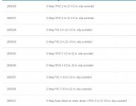
Get the CPVC, not the PVC valves.
1655853194069.png
1655853122777.png


1655853353438.png
1655853561209.png
1655853735056.png


Regarding the incorrect PN's, I got a little careless copying/pasting. I'll work on all the changes mentioned.

In the interim I'm curious about the Pentair actuators - there is an Intellivalve and a "conventional" valve actuator. It seems the Intellivalve has greater capabilities and is easier to set, therefore it's the better option (although a bit more expensive supposedly)? I agree, it's probably a good idea to use Pentair 2 and 3 port valves to ensure no issues if/when installing an actuator.

I did a little re-reading:
 

Attachments

  • Valve_Acutator_Installation_Instructions_English.pdf
    1 MB · Views: 0
For the flow switch, just contact Harwil directly and ask for the same flow switch that @wgipe got.

Below is the post from Wgipe describing their order.
Okay....so because I'm paranoid and don't want to risk my heater starving for water again...and because I like to tinker with stuff....I did some research on the proper flow switch and thought I'd document it here since I see it mentioned in several other threads, but haven't seen a project documented here where the pressure sensor was swapped out for a flow switch. Below is the email I received from Harwil. I ordered the switch today and will document the installation here so that future folks have something to refer to. I've also attached the flow switch data sheet for the recommended switch here.

======================================================================================
Hi Wes,

A flow switch that is commonly used for that application is our Q-8N series flow switch.
The part number I would recommend based on plumbing size and flow rate is Q-8N/2/2/A/VITON.
This flow switch is an adjustable flow switch with an ON set point at minimum is 44 gpm and can be adjusted up to 65 gpm in a 2” pipe.
Attached is a data sheet.

The current price for the flow switch is $148.76 each.
We do have a minimum order value of $150, so either 2 units would need to be ordered or we can round up to $150.

You are welcome to purchase direct from Harwil. For purchases we accept Visa, Mastercard, and American Express.
The shipper we use is UPS, if you have an account with UPS we can use that to ship with or just add the cost to the order total.

The email to send orders to is: [email protected]

If you have any questions just let me know.

Best Regards,
Kyle Acres
Engineering Technician
[email protected]
Ph: (805) 988-6800


Please know your ordering from us is tantamount to reading and accepting our Standard Terms & Conditions which can be found at the link below.

Harwil Standard Terms and Conditions


From: Wesley Gipe
Sent: Saturday, May 28, 2022 6:29 AM
To: Orders <[email protected]>
Subject: Which Flow Switch?

Hello,

I have a residential inground pool with a Pentair MasterTemp 4000BTU heater that I installed last year. These heaters have a pressure switch to sense flow, and for a number of reasons, I’d like to replace that with an inline flow switch. The heater manual shows 45GPM for minimum flow to operate. My plan is to place a threaded in the 2” PVC line to hold the flow switch and run the leads to the control board of the heater.

Based on that application, could you suggest and provide pricing for the flow switch that would be best for that application? Thanks!

Wes
1655858688730.png
This is the flow switch installed.

The flow switch should go on 2" plumbing into the heater.

The T that goes to the check valve bypass should be 2.5" and then reduced down to 2" to go into the flow switch T and then 2" into the heater.
 
Last edited:

Enjoying this content?

Support TFP with a donation.

Give Support
Thread Status
Hello , This thread has been inactive for over 60 days. New postings here are unlikely to be seen or responded to by other members. For better visibility, consider Starting A New Thread.