My built-in pool fountain on/off switch stopped working - it wouldn't turn off, so I replaced it but now the fountain won't turn on at all. The old switch says 20A 208/250VAC double pole switch, and it has 5 wires coming out of it - 2 load, 2 line and 1 ground. The hardware store didn't have the exact same one but they sold me a 20A double pole switch Interruptor bipolar 20A, 120/277V. The new one has screws at all 5 locations, not wires. They told me to bend the existing wires around the screws and tighten. I triple-checked that the "load" and the "line" were what they were before because I took several photos as I disconnected the broken switch, and connected the ground with a new wire from the hardware store. When I was done and switched the power back on, the fountain does not come on at all now. My question is: does "bipolar" mean it doesn't matter which side of the switch the load 1/load 2 and line 1/line 2 are connected? The new switch just says "load" at 1 end and "line" at the other end - it doesn't specify which side is load 1 or load 2. If I switched the sides of the load and line might it fix the problem or not? Any other ideas?
Need help with electrical switch for inground pool fountain
- Thread starter BB_Sacramento
- Start date
You are using an out of date browser. It may not display this or other websites correctly.
You should upgrade or use an alternative browser.
You should upgrade or use an alternative browser.
Neo5bass
0
Interrupter? As in ground fault interrupter? Does it pop the breaker when you turn it on or nothing happens? The load/ line distinction is related to how the switch opens electrically speaking. It is designed so if under heavy load over time when turned on or off the little micro-discharges that happen to every switch as they close and open have a path that won't arc out the connection. It is best to have the load on the load side of the switch.
When the breaker is open, can you measure AC going into it? When the breaker is closed but your switch is "Off" can you measure AC going into the switch? Are you running this on 120VAC or 208VAC? Just to be sure, have you stripped each wire of insulation at th switch connection point? If you are using this as a 120VAC link there should be less than a volt between Ground (pigtail "extra" wire) and Neutral (white wire) of circuit. Each pole of the switch should be symmetrical.
When the breaker is open, can you measure AC going into it? When the breaker is closed but your switch is "Off" can you measure AC going into the switch? Are you running this on 120VAC or 208VAC? Just to be sure, have you stripped each wire of insulation at th switch connection point? If you are using this as a 120VAC link there should be less than a volt between Ground (pigtail "extra" wire) and Neutral (white wire) of circuit. Each pole of the switch should be symmetrical.
I've attached a photo of the old switch and the new one's box. That might help explain. I don't know what "interruptor" means. When I try to turn the fountain on with the new switch the breaker does nothing. I don't hear or see anything. I don't have any measuring devices to measure anything. Yes, the wires are all stripped at the ends where they wrap around the screws. Do you think maybe one or more of them might not be getting good contact? Or should I hire an electrician? Thank you so much!
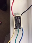
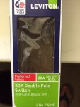


- Jun 7, 2017
- 9,156
- Pool Size
- 29000
- Surface
- Plaster
- Chlorine
- Salt Water Generator
- SWG Type
- Jandy Aquapure 1400
Line comes from your electrical source, load is what is hot only when the switch is on. They are not interchangeable. What does this power? A pump? Is it possible the pump is fried and the cause of the old switch failing? Did you test (multimeter) the red and black lines (line) to ensure they both have 120 volts when on? You can test the output lines (load) as well with a multimeter to see if the switch is working.
This switch does power a pump which circulates water to my built-in water feature in the wall of the pool. The pumps is working because the original problem was that the pump came on but would not switch off. When we pressed the switch to turn the pump off, it would click/click/click/click - you could feel it under your finger. So I changed the switch and now nothing happens. I might have to hire an electrician. I don't have a multimeter. I was just trying to verify if I connected the wiring right or not.
- Jul 21, 2013
- 53,130
- Pool Size
- 35000
- Surface
- Plaster
- Chlorine
- Salt Water Generator
- SWG Type
- Pentair Intellichlor IC-60
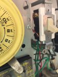
In the image above, the side showing 2 red wires attached to the switch. The top red wire is the load, and it goes behind a metal plate on the left of the picture. The lower red wire is the line and it goes down into a tube going out to the pool equipment.
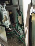
In the above image it shows the side of the switch with 2 black wires. The top wire is the load which goes behind the metal plate on the left side of the picture, and the lower black wire goes down into the circular hole at the bottom of the picture.
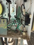
this 3rd and final picture shows it overall so you can see the whole switch and where the wires go.
- Jul 21, 2013
- 53,130
- Pool Size
- 35000
- Surface
- Plaster
- Chlorine
- Salt Water Generator
- SWG Type
- Pentair Intellichlor IC-60
I am not sure this is your problem but none of the 5 screws properly has the wires wrapped around them. Good practice is to bend the wire in a U around the stem of the screw so the screw head presses the wire down. You should not see the wire bulging out from the side of the screw head. You should also wrap the wire in a clockwise direction around the screw so that as you tighten the screw it pulls the wire tighter towards it.
You may have a wire that is not making contact between the bare wire and the screw connection. Trim the insulation back a bit more so you have bare wire wrapped around the screw stem. Needle nose pilers let you get the U bent around the screw stem.
You may have a wire that is not making contact between the bare wire and the screw connection. Trim the insulation back a bit more so you have bare wire wrapped around the screw stem. Needle nose pilers let you get the U bent around the screw stem.
YOU WERE CORRECT!! It works great now. Thanks so much - all of you. I re-did the wires so they're all clockwise then tightened the screws really well, and that did the trick. Yay!
- Jul 21, 2013
- 53,130
- Pool Size
- 35000
- Surface
- Plaster
- Chlorine
- Salt Water Generator
- SWG Type
- Pentair Intellichlor IC-60
I like to wrap black tape around my switches and outlets to cover all 4 connections. Helps prevent any thing touching live wires. A little anal maybe.
Msch99I like to wrap black tape around my switches and outlets to cover all 4 connections. Helps prevent any thing touching live wires. A little anal maybe.
Good advice. Just good operating practice to prevent a short/trip. Always in a metal box!
Thanks...
r..
Last edited:
I like to wrap black tape around my switches and outlets to cover all 4 connections. Helps prevent any thing touching live wires. A little anal maybe.
Helps prevent finger sparkies when you are in there working on next thing too. God i hate finger sparkies.
Thread Status
Hello , This thread has been inactive for over 60 days. New postings here are unlikely to be seen or responded to by other members. For better visibility, consider Starting A New Thread.

