MiniMax NT Heater - No Ignition Sequence

pickdr

0
Sep 14, 2014
36
Placentia, CA
Pool Size
23600
Surface
Plaster
Chlorine
Salt Water Generator
SWG Type
Hayward Aqua Rite Pro (T-15)
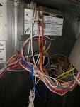
Had and E05 error. Igniter filament cracked, so I replaced it.
Now I'm getting an E04 error. The chart says ignition operating failure. Replaced the ignition system board, but still getting the error.
No gas smell, no blower, no clicks. Any idea what I should check next? Fan turns just fine, but blower never starts.
 

Attachments

  • 20200818_231848.jpg
    20200818_231848.jpg
    79.8 KB · Views: 9
  • 20200818_231928.jpg
    20200818_231928.jpg
    149.7 KB · Views: 10
  • 20200818_232002.jpg
    20200818_232002.jpg
    302.9 KB · Views: 10
  • 20200818_232213.jpg
    20200818_232213.jpg
    374.9 KB · Views: 10
You seem to be missing a wire that needs to be connected to the Fenwal ignition module. There should be a wire connected to "FS" on the ignition module that comes from the fan/blower pressure switch. I am assuming that the old and new Fenwal ignition modules have the same Catalog Number. I think that there may be a newer updated Fenwal Catalog number for replacement?
 
Wiring diagram shows it as a gray wire.

I can see the gray wire here. It looks like it splits. One goes to the main board (as the diagram suggests) and the other goes to thing in front of the gas valve. I haven't done any rewiring aside from the ignition system swap, where I switched them out one at a time, so I'm not sure if/why that would be incorrect.
 

Attachments

  • 20200819_091907.jpg
    20200819_091907.jpg
    393.5 KB · Views: 11
  • 20200818_232213.jpg
    20200818_232213.jpg
    374.9 KB · Views: 11
A little confused by your statement " Fan turns just fine, but blower never starts. ". There is only one fan/blower. Did you mean fan turns on fine, but heater never starts?
I may just be confused. When the thing is on, I can feel forced air coming out the top.
My previous house's pool heater would rumble and blow hot air. (I assumed that's what people mean by blower.) this one isn't doing that....perhaps it's not supposed to. Maybe the rumble I heard on this one was the flame?
Yes, fan turns on, but heater never starts.
 
The "gas pressure switch" before the gas valve is supposed to be in series with "thermal fuse" and connected to the main board at P7/J7 along with the other safeties. The doubled gray wire on the pressure switch below the ignition control is supposed to have one side connected to "FS" on the ignition control and the other side connected to J2 on the main control board. I see a loose blue wire to the left of the blower pressure switch that isn't connected to anything. Are you sure that it didn't accidently get disconnected and reconnected incorrectly. Could it be the P7/J7 wire that should be connected to the "gas pressure switch before the gas valve leaving the gray wire from the blower pressure switch to be connected to "FS" on the ignition control? Trace the wiring to see if this is the problem.
 
This should be the manual for your heater. http://pdfstream.manualsonline.com/7/7f5f9daa-fc69-3874-d9c3-4aa5e69a5a4e.pdf Refer to the wiring diagram on page 10. It's helpful if you print out the wiring diagram so that you don't have to look at it sideways. Make sure that the wires from the P7/J7 connection on the main board that go to the gas pressure control and thermal fuse are correctly connected. In order for the ignition control to start the firing up sequence, you need a wire connected to "FS" ( Fan Switch ) on the ignition module in order to prove that the Fan/Blower is working correctly or it will not attempt to fire up.
 

Enjoying this content?

Support TFP with a donation.

Give Support
OK, just spent a couple hours going through all the wiring. No dice.
The only discrepancy is that on the wiring diagram, FS is Flame Sensor (not fan switch), and my unit doesn't have one as far as I can tell, unless it's tucked away somewhere. Not even an extra wire that could go to it. The extra blue wire you see is for 120 VAC, but this unit is wired up for 240 VAC, so that blue wire is not used.

This diagram also doesn't include a gas pressure switch as far as I can tell. My wiring has TH on the igniter board connected to the gas pressure switch with a white wire, instead of an orange wire going to the main board as indicated on the diagram. My orange wire from the main board goes to the transformer, rather than the ignition system. I didn't touch that connection (haven't touched the main board) so I left it as is since it worked that way before.

I traced J7 as you suggested, and it connects to the water pressure switch around back. As indicated on the wiring diagram.
 
I'm reading about "lock out." Is it possible I'm in "Hard Lock Out," and just haven't given it an hour to expire? I've shut off power multiple times since checking wiring and stuff, so I figure that would reset it....but who knows.
 
I think that the wiring diagram that we are looking at is not applicable to your heater. Do you have a wiring diagram on one of your covers or cabinet walls? Do you have a multimeter? I have located a wiring diagram for the Fenwal 05-33 and should be able to help if you have a multimeter.
 
Just as a guess, it would seem that the wiring at the ignition control should show 24Vac between "IND" and "GND" to start the Fan/Blower ( which it does ). Also as a guess, it would seem that the gas pressure switch, thermal fuse and blower/fan air pressure switch are all wired in series ending at the TH terminal on the ignition control from what you have mentioned as to the wiring. I am guessing that you have the Blower/Fan running but you do not have 24Vac between GND and TH on the ignition control. This would mean that you are losing the 24 Vac in the series circuit that contains the gas pressure switch, Thermal Fuse and the blower air pressure switch. You should have 24Vac from GND on the ignition control to both wires on the gas pressure switch, both wires on the Thermal Fuse (just above the ignitor) and also the blower air pressure switch at the Common and NO ( normally open ) contacts. I suspect that you are losing the 24Vac at the blower air pressure switch, but it could also be either the gas pressure switch or the thermal fuse
 
Between IND & GND I have 25.1 VAC
Between TH & GND I have 20 VAC
Between Air Pressure Swich & GND I was only getting 4 VAC.
Should that be 24 VAC as well, or does that not receive the 24 until the gas pressure switch switches?

I'm not super multimeter savvy, so hopefully my poking and prodding was correct.
 

Attachments

  • 20200820_221520.jpg
    20200820_221520.jpg
    357.4 KB · Views: 5
  • 20200820_221437.jpg
    20200820_221437.jpg
    277.3 KB · Views: 4
  • 20200820_222547.jpg
    20200820_222547.jpg
    365.9 KB · Views: 4

Enjoying this content?

Support TFP with a donation.

Give Support
Thread Status
Hello , This thread has been inactive for over 60 days. New postings here are unlikely to be seen or responded to by other members. For better visibility, consider Starting A New Thread.