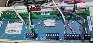
Max-E Therm SR400LP - Control Board LED doesn't come on

Looking at the chart it may be voltage on IND and not FN that tells the Fenwal to start the blower. Check for 24V on IND as the chart asks.
It looks like the flowchart just says to confirm 24v between "24 VAC" and Grnd... and only to check to make sure IND is wired correctly. Being I haven't changed any wiring and it worked before, I will have to assume wiring is fine. I've checked for 24v between "24 VAC" and Grnd. We're good there. So that seems to lead me down to jumping F1 and F2 together to confirm the blower works. And from there, if it does, it says to replace the Fenwal.

I'll let you know tomorrow what the outcome of that test is. Thanks again for your patience and help!!!!
 
It looks like the flowchart just says to confirm 24v between "24 VAC" and Grnd... and only to check to make sure IND is wired correctly. Being I haven't changed any wiring and it worked before, I will have to assume wiring is fine. I've checked for 24v between "24 VAC" and Grnd. We're good there. So that seems to lead me down to jumping F1 and F2 together to confirm the blower works. And from there, if it does, it says to replace the Fenwal.

I think something is missing from the diagnostic flow chart. The Fenwal operation is described in....


Fenwal says:

Start Up - Heat Mode
When a call for heat is received from the thermostat supply in 24VAC to TH/W, the control will reset, perform a self-check routine, flash the diagnostic LED and begin a pre-purge delay.
Following the pre-purge period, the gas valve is energized and sparking commences for the Trial For Ignition (TFI) period.


24VAV in TH/W is what tells the Fenwal to start the ignition process and start the blower on heaters that use the blower.
Thanks for looking that up Allen. I'll confirm TH again tomorrow. When I tested it (similar to how I screwed up the other test) I was under the impression the Fenwal was going to have an output of 24v at TH. I didn't check the TH wire itself coming from the PCB. I'll confirm it tomorrow but I'll bet I'm getting 24V from the PCB to TH.
 
I'll confirm it tomorrow but I'll bet I'm getting 24V from the PCB to TH.

If you have 24V from PCB to TH then it points to a bad relay in the Fenwal.

Some people have opened up the Fenwal box and replaced the relay if you can do soldering.
 
If you have 24V from PCB to TH then it points to a bad relay in the Fenwal.

Some people have opened up the Fenwal box and replaced the relay if you can do soldering.
I've learned quite a bit in this short stint with you explaining things Allen. I very much appreciate it! My soldering skills are sloppy at best so I'll probably just price one (if it's confirmed to be bad) and order a PCB for the Intellicenter too. That's a real bummer on the latter given everything else works on the darn thing except that one little relay.
 
Here is what one member found...


I opened up my old fenwal and the circuit trace from the relay to the blower terminals was completely nuked. I think the heater was struck by lightning or something over the winter.
 
I've learned quite a bit in this short stint with you explaining things Allen. I very much appreciate it! My soldering skills are sloppy at best so I'll probably just price one (if it's confirmed to be bad) and order a PCB for the Intellicenter too. That's a real bummer on the latter given everything else works on the darn thing except that one little relay.

If you replace your IntelliCenter PCB consider sending the bad one to @ogdento

He is collecting them and trying to analyze why we see so many IntelliCenter boards bricked by storms.

Maybe Tom will come up with some board repair procedures.
 
Thanks for that link Allen and the suggestion on the board. If the Fenwal ends up needing replaced, I will definitely have to open it up now... just to see if the relay is smoked or anything else shows signs of lighting surge. It would make sense as we believe the lightning traveled into my pool cage/enclosure and then into an outlet that's wired on it and back to the subpanel (Intellicenter panel). The outlet is on the bottom of the subpanel... and you can guess what the next breaker above it is... yep, the heater. So I'm sure it grabbed the next thing it could and traveled out to the heater and hit the Fenwal.
 
Do you have a Surge Suppressor on your IntelliCenter Panel?


The bottom breaker in my Intellicenter is a 20A 240V connected to a FirstSurge FS140 and I still had an IntelliCenter PCB bricked in a storm.

 
Do you have a Surge Suppressor on your IntelliCenter Panel?


The bottom breaker in my Intellicenter is a 20A 240V connected to a FirstSurge FS140 and I still had an IntelliCenter PCB bricked in a storm.

I have a CB surge protector in my main panel (but none in my subpanels). I believe it's primary purpose is to take a surge that comes in the "front door" (main line) and shunt it before it makes it further down the breaker panel to other circuits. Unfortunately, when the lightning strike isn't direct and affecting a main line, all bets are off as lightning can do some crazy things. This lightning strike hit a 60-70 pine tree in our back yard jumped to a carport, then jumped into my shop, fried a minisplit AC on the way, took out some of the electronics in my motorhome (that's still in the shop), jumped into the ground, fried my sprinkler controler box in the shop, jumped into the pool structure and pool, fried a breaker for an outlet on the pool cage, fried one pool LED light and made the other so it's stuck on "blue" now (which we like blue anyway), then made it's way from that outlet on the pool cage to the Intellicenter subpanel and then into the heater. It seemed to travel backwards to the main panel too and flipped a breaker there. It cooked about 3 or 4 exterier LED light fixture bulbs, an LED 4'er light in the shop, and one an LED bulb in the house. It took out my internet router (modem was fine) and an eithernet switch box, cooked a battery charger in my boat and I'm probably missing something else or two... Crazy how it makes its way.
 

Enjoying this content?

Support TFP with a donation.

Give Support
Then you have the connection diagram that Allen posted from page 30 and also the ladder diagram from page 31 of the manual. The ladder diagram may give you a better understanding of the sequence of operation and what points to test for voltages. If you look at the ladder diagram you will see that if the heater is asking for heat the first point to check would be the common side of the water pressure switch. If you look at the control board at the 8 pin connector on the left side the uppermost connection is the common side of the water pressure switch and you should have 24V between GND and that top connection. Testing downward you should have 24V between GND and the first 7 connections if the high limit switch is closed. If you follow the ladder diagram you should then have 24V to IND on the Fenwal which will operate the blower relay to close the NO F1-F2 contacts and start the blower closing the air flow switch and putting 24V to TH which should start the ignition sequence that is normally listed on the Fenwal. Try tracing through the sequence connections to see what is happening.
 
Then you have the connection diagram that Allen posted from page 30 and also the ladder diagram from page 31 of the manual. The ladder diagram may give you a better understanding of the sequence of operation and what points to test for voltages. If you look at the ladder diagram you will see that if the heater is asking for heat the first point to check would be the common side of the water pressure switch. If you look at the control board at the 8 pin connector on the left side the uppermost connection is the common side of the water pressure switch and you should have 24V between GND and that top connection. Testing downward you should have 24V between GND and the first 7 connections if the high limit switch is closed. If you follow the ladder diagram you should then have 24V to IND on the Fenwal which will operate the blower relay to close the NO F1-F2 contacts and start the blower closing the air flow switch and putting 24V to TH which should start the ignition sequence that is normally listed on the Fenwal. Try tracing through the sequence connections to see what is happening.
Thanks for the insight on the ladder diagram in the manual. I will check it out and see if I can follow it, etc. Much appreciated!!
 
Final Test Report/Prognosis. Looks like the FENWAL needs replaced on the heater and a new PCB on the IntilliCenter. I tested the 24v on the heater from the PCB on the IND line when the heater is calling for heat. It indeed produces 24V. Due to such, the FENWAL should close down the relay to power up the Blower, unfortunately it does not. The relay stays open (confirmed w/continuity test). I also jumper'd power direct to the blower (connected F1 to F2) and the blower powers right up. So I'll order a new FENWAL ignition control module. As for the IntelliCenter - I retested the heater relay on the back of the board for when the IntelliCenter is calling for the heater. The relay never closes, confirmed with continuity test. So a new board for the IntelliCenter will be ordered as well.

Thanks for the help on this - it's GREATLY appreciated. I will report back once the parts are installed to conclude this thread. Stay tuned.
 
not heater related... but it seems like your intellicenter mostly survived a lightning strike, which is a bit of a novelty!

I think - and am hoping - that @ajw22 is correct about either the relay driver or relay being bad... if you get some time, inspect the areas circled in red and blue where the relay drivers and heater relay, respectively, are soldered: (send a pic if you see any burns or bubbled/melted chips)

1724246734581.png
 
not heater related... but it seems like your intellicenter mostly survived a lightning strike, which is a bit of a novelty!

I think - and am hoping - that @ajw22 is correct about either the relay driver or relay being bad... if you get some time, inspect the areas circled in red and blue where the relay drivers and heater relay, respectively, are soldered: (send a pic if you see any burns or bubbled/melted chips)
Thanks for the suggestion and response Tom. Here's a couple pics of my board. I believe the drivers will be on the other side of the board in my case, so I'll have to check that out once the new board arrives and I remove this one. The relay however, next to the heater output terminals, doesn't look damaged on the outside.
 

Attachments

  • 20240821_093451.jpg
    20240821_093451.jpg
    404.2 KB · Views: 4
  • 20240821_093500.jpg
    20240821_093500.jpg
    232.3 KB · Views: 4
If the only component bad on the board is the small heater relay, it can be had for a few dollars from ebay or digikey but you need to work with a soldering iron. Not sure if it's up your alley but lots cheaper then a new board.
 
  • Like
Reactions: 1000RR
If the only component bad on the board is the small heater relay, it can be had for a few dollars from ebay or digikey but you need to work with a soldering iron. Not sure if it's up your alley but lots cheaper then a new board.
If I solder it back in, it would be one BIG blob of solder sitting there. I suck at it. LOL. I appreciate the suggest though. At a minimum, at least I'll have a backup board that will operate everything except the heater - so I guess there's that.
 

Enjoying this content?

Support TFP with a donation.

Give Support
Thread Status
Hello , This thread has been inactive for over 60 days. New postings here are unlikely to be seen or responded to by other members. For better visibility, consider Starting A New Thread.