Main pump and booster stopped working after replacing timer

actx

Member
May 10, 2020
9
Dallas
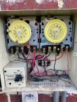
Hello. I replaced one of two timers on my pool yesterday (I have done this before). Prior to replacement, the booster pump timer didn't move but the switched worked and allowed me to manually turn on the Polaris. As I said, I have done this before and here was my procedure:
1. Turn off power at the breaker.
2. Turn off the on/off switch the feeds into the timer box.
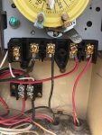
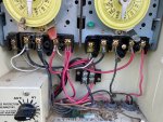
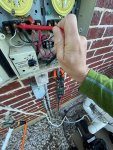
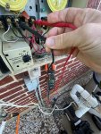
3. Take photos of the connections
4. Remove the old timer and move the wires to the new timer
5. Place new timer in box
6. Turn on breaker
7. Turn on the on/off switch the feeds into the timer box
8. Turn on the main and booster pump timer - NOTHING.

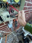
I am getting nothing when they are turned on. No sound whatsoever from either pump. I reconfirmed wiring (correct) and tested the electrical. An electrician friend of mine came over and tested everything from the box to the switch to the timer and from the timer to the pumps (actually removed the pump covers and confirmed that electricity was getting to the pumps. The capacitors look good.

I am lost. I cannot figure out what is going on. The switches on the timer work. they are sending electricity at the correct voltage when they are turned on (120 / side).

I cannot believe that both pumps burnt out at the same time.

Help!
 
AC,

"Main pump and booster stopped working after replacing timer"

In the troubleshooting business, we call that a clue... :mrgreen:

A quick recap.. It worked, I screwed with it... It now no longer works... This almost always means we installed the problem with our actions.

How about a bunch of pics showing the overall system and then the wiring inside each box/timer.. Maybe one of the guys here can spot something, or we can at least be speaking the same language when we ask you to measure something.


they are sending electricity at the correct voltage when they are turned on (120 / side).

What does this mean? If you are trying to measure 240 into a pump, you can NOT measure L1 to ground and L2 to ground and add them together.. You MUST measure between L1 and L2.. If you had 240 at the input to the pump it would run, or the pump would have to be bad.


Thanks,

Jim R.
 
AC,

"Main pump and booster stopped working after replacing timer"

In the troubleshooting business, we call that a clue... :mrgreen:

A quick recap.. It worked, I screwed with it... It now no longer works... This almost always means we installed the problem with our actions.

How about a bunch of pics showing the overall system and then the wiring inside each box/timer.. Maybe one of the guys here can spot something, or we can at least be speaking the same language when we ask you to measure something.


What does this mean? If you are trying to measure 240 into a pump, you can NOT measure L1 to ground and L2 to ground and add them together.. You MUST measure between L1 and L2.. If you had 240 at the input to the pump it would run, or the pump would have to be bad.


Thanks,

Jim R.
Good catch! I wasn't even thinking about that. Switch a couple hots inside the timer box and you're feeding both sides 120 in the same phase!
 
Thanks for all the replies. . .here are some photos. . .
Photo 1 - right side (booster pump) BEFORE replacement
Photo 2 - Both left/right after replacement
Photo 3 - Both left/right after replacement close up
 

Attachments

  • Photo 1.jpeg
    Photo 1.jpeg
    290.8 KB · Views: 7
  • Photo 2.jpeg
    Photo 2.jpeg
    417.5 KB · Views: 7
  • Photo 3.jpeg
    Photo 3.jpeg
    385.3 KB · Views: 9
Also, here are some readings with a volt meter on the main pump side (similar on the booster).
Photo 4 is the reading from the red wire of 122
Photo 5 is the reading from the black wire of 122
Photo 6 is them together and they read 1.4?
 

Attachments

  • Photo 4.jpeg
    Photo 4.jpeg
    518.3 KB · Views: 4
  • Photo 5.jpeg
    Photo 5.jpeg
    507.9 KB · Views: 5
  • Photo 6.jpeg
    Photo 6.jpeg
    449.4 KB · Views: 5
AC,

"Main pump and booster stopped working after replacing timer"

In the troubleshooting business, we call that a clue... :mrgreen:

A quick recap.. It worked, I screwed with it... It now no longer works... This almost always means we installed the problem with our actions.

How about a bunch of pics showing the overall system and then the wiring inside each box/timer.. Maybe one of the guys here can spot something, or we can at least be speaking the same language when we ask you to measure something.


What does this mean? If you are trying to measure 240 into a pump, you can NOT measure L1 to ground and L2 to ground and add them together.. You MUST measure between L1 and L2.. If you had 240 at the input to the pump it would run, or the pump would have to be bad.


Thanks,

Jim R.

Jim - so can you walk me throught this so I can confirm? If i place the meter probes on red/red and black/black at the pump it should read 240? Not 120 on each side to ground?

Thanks
 
your voltmeter probes are on the load side (switched side to pump) What do you get from the line side L1 to L2 (from breaker) of the left timer with timer switched off and also with timer on? Also the right side will only have line power (and potentional to provide power when timer is on, through load contacts) when the left timer is on. Does the line side power switch on and off on the right timer when the left timer is turned on and off?
 
Last edited:

Enjoying this content?

Support TFP with a donation.

Give Support
The schematic below shows similar to what you have with the freeze protection thermostat. There are three sets of each color, black and red in your box. This diagram only shows two of each color to the relay but I count three each in your box. Turn off power at the breaker, turn timers to off and check with ohms setting for commonality between each of the red and then each of the black wires. I suspect the third wire goes to the thermostat breaker contact and is not common when the breaker is not energized.


1589221906377.png
 
Jim - so can you walk me throught this so I can confirm? If i place the meter probes on red/red and black/black at the pump it should read 240? Not 120 on each side to ground?

When a motor is in the circuit, you can get a false reading if you measure L1 to gnd and L2 to gnd.. You must always measure between L1 and L2 when measuring 240 volts.

Jim R.
 
AC,

Photo 4 is the reading from the red wire of 122
Photo 5 is the reading from the black wire of 122
Photo 6 is them together and they read 1.4?

You are simply missing either L1 or L2.. In photo 6 when you measure between pins 2 and 4 you get basically nothing, because you are missing either L1 or L2

What voltage do you get when you measure between the red and black wires on the small 4 pin terminal block?

Thanks,

Jim R.
 
I think this was it! I was getting 120 on each going to ground which I thought was correct. But not 240 going L1 and L2. I went back to the breaker box and checked there and got very similar results. 120 each going to ground but NOT 240 when going L1 and L2 (it would something like 20). I replaced the breaker at the box and boom! The pumps worked. I then retested and am getting 240 going L1 and L2 at both the box and the pump.

Thanks a bunch to all!

When a motor is in the circuit, you can get a false reading if you measure L1 to gnd and L2 to gnd.. You must always measure between L1 and L2 when measuring 240 volts.

Jim R.
 
  • Like
Reactions: JamesW
Thread Status
Hello , This thread has been inactive for over 60 days. New postings here are unlikely to be seen or responded to by other members. For better visibility, consider Starting A New Thread.