Low Voltage for Valve Actuators

olevelo

Well-known member
Jul 1, 2023
79
Niceville, FL
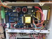
I'm only getting a max of 22-23 VAC, with a quick dropoff in use and a slow build after, on my panel (Aqualogic PS4). Is there any hope?

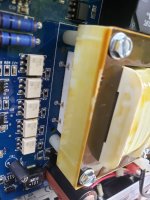
I bought my house with pool about a year ago, and none of the 3 valve actuators were working. There was a little hum to them, and a couple of them would start turning if you gave it a push while on, but for the most part they just didn't do anything. Had someone check it out when I was getting my heater installed. He checked the voltage at the panel and said it was fine, so said the actuators were all bad and needed replaced. I put it off and finally got new ones (admittedly I did cheap out and got Tork), but after trying them out (both on the valve housing and off), I'm getting the same result. So I checked the voltage myself and found what I said above...never even hitting 24V, and a massive "discharge" when trying to use it. I'm guessing it's a bad capacitor? It happens to all of the valve sockets simultaneously.

Is there any easy fix to this, or does this require some electrical expertise, or is this where I give up and get a whole new panel? I'd really like to be able to switch between pool and spa, and turn the cleaner on, without manually turning valves!
 
O,

I really doubt that only having 22 or 23 VAC would make any difference in the operation of an actuator.

Each valve driver has a relay, that selects which way the valve moves. So it is unlikely that all three relays are bad.

I suspect that when you test with no load it measures about 24 VAC, but when you try to use the actuator, there is just not enough current to actually drive the actuator motors. This what you are seeing when the voltage drops way off.

I normally believe that most transformers do not go bad, or at least not very often. But, in this case, it seems to me the transformer is bad due to internal resistance, or something between the transformer and the three valve relays has some resistance. I'd want to check the connection points where the transformer connects to the main card.

Thanks,

Jim R.
 
To clarify, the drop to 10-15V (or more) is not while the actuator is running, it's AFTER. And then it takes several more minutes until the voltage returns to 22-23V.

Any idea which transformer is used? Seems like there were a few, and none near the connectors (BTW there are 4 valve ports, just not using the 4th).
 
O,

Sorry, I am a Pentair kind of guy and have no direct experience with Hayward stuff, but all of these system work about the same way.

Are you sure you have a number of transformers?? I find that odd, as I would have expected it to be just one or maybe two. On my Pentair automation there is one transformer that powers everything but the SWCG..

If you got it opened up show us some pics..

Thanks,

Jim R.
 
It's closed up and dark now, but found this online and it looks like it. Apparently I'm dumb as it does look like it only has one transformer. I was thinking about capacitors, as that was my initial thought, given the slow "recharge". Does the transformer only control the valve actuators tho? Cause everything else works fine.
 

Attachments

  • Screenshot_20230701-212321_eBay.jpg
    Screenshot_20230701-212321_eBay.jpg
    215.9 KB · Views: 9
O,

I had assumed the transformer was external to the Circuit card.. But, either way, I suspect that your transformer has several different voltage outputs. I don't so much believe that the transformer is "bad", as much as I believe that there is some connection that has resistance that should not be there.

Let's assume that the card you show is exactly what you have.. Then I would be looking for a bad solder joint the shows some signs of heat damage or a poor solder job. Somehow the voltage has to get from the transformer to the 4 valve relays and then to the valve connectors. I suspect that one of those connection point is bad. And.. it could be internal to the transformer, but that would be my last "guess"... :mrgreen:

Thanks,

Jim R.
 
Hmm, looking at other photos, I think I do have another larger transformer next to the board.

Doing some more research I found that the OmniPL Retrofit finally became available, and is pretty tempting. But now worried that the problem is actually in the bigger transformer so swapping to the OmniPL wouldn't actually help.
 
Here's my actual panel. I found a video that had some troubleshooting, mostly for the salt cell working, and it said the yellow wire should be 20-24V. So checked it, and it does the same thing as at the valve pins, where it starts off good but after running an actuator it rapidly drops and slowly builds back. Since that's direct at the transformer, I assume that means the transformer has a problem. The salt cell works fine though, so it's a bit baffling. Not sure if there could be an issue elsewhere on the board that could cause that.

More and more tempted to just try the OmniPL upgrade, and then if it still does this, I know it's the transformer. It would be cheaper to do the transformer first but also a waste of money if it doesn't work, while I know I want the upgrade either way...just don't know if I want it $1500 bad!
 

Attachments

  • 20230702_112820.jpg
    20230702_112820.jpg
    566.4 KB · Views: 23
O,

I suspect the big transformer is just for the salt cell and the little transformer is for everything else.

Have you taken the circuit card out and inspected the bottom side?

Thanks,

Jim R.
 

Enjoying this content?

Support TFP with a donation.

Give Support
I wondered that, but it doesn't look like the OmniPL upgrade has a transformer on it at all, and it requires the old transformer as part of the install. And the fact that the same voltage drop appears at that terminal indicates that it's used in some way when the actuators are used.

I didn't pull the whole board off as it looks like it would require disconnecting quite a bit of stuff. Not sure I want to go to the effort of taking it all apart, then putting it back together, just to take it apart again if I'm going to upgrade the board. Or if it seems likely it's that transformer and I just replace it.
 
  • Like
Reactions: Jimrahbe
That looks like what I found for trouble shooting the salt cell too. Just not understanding why I'm not seeing any issues with it if there were a problem. Guess I can check this tho. Need to wait a bit for my cleaning cycle to finish tho.
 
The transformer on the board has 4 screws, maybe try taking that off to see if you can test it or find a part number to replace it.

20230702_112820-jpg.509666
 
It looks like it's surface mounted so not inclined to try pulling it off! But it has markings right on top. Looks like it does have a 23V output. But does the OmniPL Retrofit have a transformer too? The pics don't look like it. About to try the other test on the main transformer.
 

Attachments

  • 20230702_173436.jpg
    20230702_173436.jpg
    343 KB · Views: 2
  • 20230702_173451.jpg
    20230702_173451.jpg
    319.5 KB · Views: 2
OK, did the other test, and the violet and gray was good, but the white and blue was 0 ohms! So guess it's the transformer. I'm just baffled why the salt cell seems to be fine. Guess I'll go ahead and get a transformer. Still really tempted by the OmniPL tho!
 
  • Like
Reactions: JamesW

Enjoying this content?

Support TFP with a donation.

Give Support
Thread Status
Hello , This thread has been inactive for over 60 days. New postings here are unlikely to be seen or responded to by other members. For better visibility, consider Starting A New Thread.