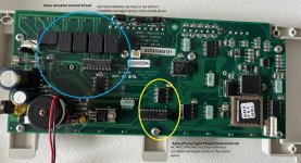
Jandy Variable-Speed Epump runs for a random length of time (hours/days), then goes offline.

Maybe a bad Relay or Relay Driver.

Aqualink Relays or JVAs Not Working.​

You could have a failed driver chip. The Driver Chips can be thought of as a series of small relays. When one of the Driver Chips receives a signal, it closes a contact which passes 24 VDC to the appropriate relay coil socket, in this case AUX 1. Each relay driver chip activates a specific set of relay coil sockets (see the chart below). If a Driver Chip fails, it is usually caused by either shorted relay coil wires, a shorted relay coil, or a relay not designed for the 24 VDC coil voltage (i.e., 24 VAC rather than 24 VDC).
https://www.troublefreepool.com/wik...ualink_RS#Aqualink_Relays_or_JVAs_Not_Working
 
The pool lights are a problem. I have two lights. Both come on for a few seconds, then one goes off completely while the second starts blinking like a strobe light.
With multiple relays malfunctioning, the relay driver is the likely problem.

The relay drivers are in sockets and they should be easy to replace.

Post pictures of the circuit board if you can.

$2.42 each is a low cost to see if that fixes the problem.
 

Enjoying this content?

Support TFP with a donation.

Give Support
I was thinking that maybe the aux relays were bad and affecting the relay driver causing it to shut off the power to the pump relay.

If you unplug the light aux relays from the sockets, will the pump stay on?

Can you show the wiring in the box including the relay wiring?

Is the pump powered through the Filter Relay?

If yes, can you take it off of the relay and power it directly?

What breakers go to which equipment?

I would probably just try replacing the relay drivers now that you are indicating that multiple relays are malfunctioning.

Can you show the front and back of the control circuit board?
 
What did you unplug?

You have to unplug the relay coil wire plugs from the relay sockets so that the aux relays are not able to affect the relay driver.

At this point, I would probably just get new relay drivers and replace the existing drivers.

Make sure that you document the direction and orientation of the drivers before removing them to make sure that the new ones go in the same direction.

If you take the pump off of the Filter Pump relay, you need a way to turn it off at the equipment pad if necessary.

1734059154505.png
 
You have to unplug the relay coil wire plugs from the relay sockets so that the aux relays are not able to affect the relay driver.

Note this from the Jandy Troubleshooting Manual:

The relay coil provides resistance (approximately 300 Ohms); if there is no resistance, the driver chip circuit will be damaged.

Do not turn on any AUX that does not have a relay plugged into it.


Make sure that you document the direction and orientation of the drivers before removing them to make sure that the new ones go in the same direction.

When replacing the ULN2803A chip, note the orientation of the cutout on one edge and install the new chip with the same orientation.
ULN2803_Pinout.png
 
Do not turn on any AUX that does not have a relay plugged into it.
An open line is ok and not a risk.

An open line has infinite resistance and no current will flow.

They are referring to a short, which will allow too much current to flow and damage the relay driver.

I suspect that the cycling relay might be shorting out and affecting the relay driver or the relay driver is defective and affecting the relays.

I would replace the relay driver and check the resistance of the relay coils.

The resistance of the relay coil should be the same for all relays and about 300 ohms.

If the resistance is incorrect for a relay, replace the relay and do not plug it in.

If you have an unused relay, you can use that or get a new relay.


your relay transistors maybe bad. I recently had to replace mine after a surge. My symtoms included one of my outputs/relays was always hot (button didn't turn it off), also my poot heater wouldn't come on (firemans switch used by ET closes a circuit).

There are two ULN2803A chips that control all the inputs/outputs (8 on each chip) to all devices on the board. Surge can take some of the transistors out.
Check my video out. I have all info in the description of the video for the parts.

 
TypeDescriptionSelect All
CategoryRelays
Power Relays, Over 2 Amps
MfrOmron Electronics Inc-EMC Div
SeriesG7L
PackagingBulk
Part StatusActive
Mounting TypeChassis Mount
Coil Voltage24VDC
Contact FormDPST-NO (2 Form A)
Contact Rating (Current)25 A
Switching Voltage250VAC - Max
Load - Max Switching6250VA
Coil Current79 mA
Coil TypeNon Latching
FeaturesTest Button
Termination StyleScrew Terminal
Seal Rating-
Coil InsulationClass B
Must Operate Voltage18 VDC
Must Release Voltage3.6 VDC
Operate Time30 ms
Release Time30 ms
Operating Temperature-25°C ~ 60°C
Contact MaterialSilver Alloy
Approval AgencyCSA, TUV, UR
Relay TypeGeneral Purpose
Grade-
Qualification-
Coil Resistance303 Ohms
Base Product NumberG7L-2A
 
#1 should be the Filter Pump Relay Coil Power Plug.

#2 and #3 should be the Filter Pump Relay Coil Terminals.

Unplug the plug and measure the resistance from #2 to #3 and it should be about 300 ohms.

Do this for each relay.

Make sure that the power is off.
1734104544931.png
Aqualink RS.jpg

1734104851254.png
 

Enjoying this content?

Support TFP with a donation.

Give Support
Thread Status
Hello , This thread has been inactive for over 60 days. New postings here are unlikely to be seen or responded to by other members. For better visibility, consider Starting A New Thread.