Jandy LXI 400 Fault Ign Controller

KetMalice

Member
May 9, 2023
7
Oklahoma
I’m working on my father-in-laws pool and I could use some help. I’ve read through some literature about this issue on the internet.

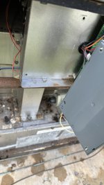
I’m getting 26 volts to the fenwal. When I kick the heater on it faults on the LCD display on the outside of the heater, the fenwal never flashes its red light to tell me where the fault lies. Does that mean the fenwal is dead? Is there an output I can test voltage on to see if the fenwal is working?

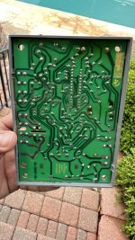
We have a family event on Friday so I’m really trying to get this going for that. I’ve ordered a new fenwal and power distribution board from Amazon to try.

IMG_7075.jpeg
 
26 volts at what Fenwal terminals? You should always have 24 volts between the GND and 24VAC terminals. Heating sequence is initiated by 24V between GND and W terminals which closes fan/blower contacts F1/F2 to power the fan/blower. After the blower starts, the airflow switch closes to give 24V between GND and PS which will start the actual ignition sequence. Then you go through prepurge, ignitor warm up, power to gas valve and flame proving (rectification).
 
So I took the leads off of ground and 24 vac and tested them. I sort of understand what you are saying but I don’t understand how to test the other things you are saying. Do I take the leads off and test the terminal on the fenwal itself to see if it starts trying to send power somewhere?


IMG_7140.jpeg
 
You can do your testing with one meter lead attached to ground (case ground should be fine, where green wire is attached to cabinet on right side). Use the other lead to check for voltage with or without the wire attached, but realize that if the wire is not attached the control will not function.
 
You can do your testing with one meter lead attached to ground (case ground should be fine, where green wire is attached to cabinet on right side). Use the other lead to check for voltage with or without the wire attached, but realize that if the wire is not attached the control will not function.
My new fenwal will get here today, we had a really hard rain last night and I just so happened to go out and test voltage today. There was water in the fenwal, and it looks in the bottom right of the board one of the circuits has major corrosion.
 

Attachments

  • IMG_7178.jpeg
    IMG_7178.jpeg
    270.3 KB · Views: 6
  • IMG_7180.jpeg
    IMG_7180.jpeg
    415.4 KB · Views: 6
You can do your testing with one meter lead attached to ground (case ground should be fine, where green wire is attached to cabinet on right side). Use the other lead to check for voltage with or without the wire attached, but realize that if the wire is not attached the control will not function.
The new Fenwal did not fix it. I’m sorry, I’m fairly ignorant about this. How do I check the voltage with the wires drill attached?

Edited: I guess use a clamp meter?
 
Last edited:
26 volts at what Fenwal terminals? You should always have 24 volts between the GND and 24VAC terminals. Heating sequence is initiated by 24V between GND and W terminals which closes fan/blower contacts F1/F2 to power the fan/blower. After the blower starts, the airflow switch closes to give 24V between GND and PS which will start the actual ignition sequence. Then you go through prepurge, ignitor warm up, power to gas valve and flame proving (rectification).
Sorry, hit quite and then refreshed and it posted it
 
Thread Status
Hello , This thread has been inactive for over 60 days. New postings here are unlikely to be seen or responded to by other members. For better visibility, consider Starting A New Thread.