Intermatic Timer 220v wiring to motor, breaker, Fpl on call

Mitzi

New member
Mar 30, 2019
4
Miami
Hello,

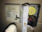
My pool motor blew up the other day. I hired a pool technician to fix. They replaced the pool motor with a century Ust1102 1hp. After the install, they said the timer is blown and I will need to replace that as well. The timer is an intermatic timer 220v.

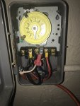
In the pic you see there, the two black cables on the right opening are coming from the breaker. The orange tube on the bottom opening is coming from the pool motor. The red and blue cable on the left opening, are coming from the FPL on call box.

I tried turning off the pump after the install at the timer and it shocked me. I went to the circuit breaker and I turned off everything going to the pool.

I got to investigating on YouTube and here and I think the wiring is wrong. He charged me 300 for the motor and the fix.

What needs to be corrected? I need to find someone to fix but I wanna know what needs to be done before I hire anyone. Thank you.
 

Attachments

  • F7C9733F-F86B-46BB-9BF7-61332D06C7A0.jpeg
    F7C9733F-F86B-46BB-9BF7-61332D06C7A0.jpeg
    370.3 KB · Views: 47
Mitzi,

The first thing I notice is there is no green ground wire going to the the pump. It looks like the installer just used an old piece of extension cord. A 220 volt pump should have two 120 volt lines, L1 and L2 which make up the 220 volts and a green ground wire.

I don't see anything wrong with the way the timer and FPL are wired, except I am not a fan of only turning off just one of the two power lines going to the pump. I would have the timer shut off both lines..

The problem that I see is that the original install appears to never have had a ground.. If it did, you would have three wires coming from the circuit breaker input.. L1, L2 and ground. Maybe they are using the conduit as the ground, but this was not carried to the pump, nor do I know if that is even allowed for a pool pump..

Let me call @ajw22 who actually knows what he is talking about, and see what he thinks..

Thanks,

Jim R.
 
  • Like
Reactions: Mitzi
What model is that Intermatic timer? It should be a T104M. You can't go by the model number on the door since it looks like only the mechanism was replaced and not the housing.

It is definitely wired wrong in multiple ways:

- no ground from pump to timer.
- no ground from timer to breaker panel
- one 220V leg always hot and not switched which is why you were shocked when the timer was off
- pool pump wiring must be in conduit

The red wire from the FPL box should be on the empty right most screw to make it switched rather then always hot. I am not familiar with the FPL box and how that complicates the wiring.

There is a thin white wire coiled behind all the wires and I don't know what that is connected to or for.

You need a competent electrician to clean this up and do it right and to code..
 
  • Like
Reactions: Mitzi and Jimrahbe
Thank you for your reply, Allen. Yes, it is a intermatic t104m. The FPL box is an energy management tool. It is required for pool pumps down in Florida. The thin white wires are the timers motor cables. I reached out to a pool electrician via yelp. Let’s see how it goes.
 
The white wires behind the colored wires probably go to the timeclock.

It doesn’t make sense that there are three incoming colored wires. That implies that all three are hot unless one is a neutral or ground and the wrong color.

If they are all hot, then there must be at least 2 breakers. Maybe a 120 breaker and a 240 breaker?

You definitely need an electrician to clean it up and wire it correctly.

You shouldn’t be getting a shock in any case unless one of the wires is connecting to ground.

The pump should be on a GFCI breaker.

Do you have a picture of the wiring at the pump?

What do the 2 black wires going out to the right go to?
 
There are three wires from the FPL.. The black wire connected to pin 1 supplies power to the FPL's electronics.. The Red wire connected to pin 3 supplies the input to a relay inside the FPL. The output of the relay is the blue/purple wire which goes to the pump. Basically when the power company whats to shed some none-vital loads, they turn the FPL on, which opens the relay and shuts the pump off. I find it odd that they only interrupt just half of the 220 power but that is what they do..

Jim R.
 

Enjoying this content?

Support TFP with a donation.

Give Support
There are three wires from the FPL.. The black wire connected to pin 1 supplies power to the FPL's electronics.. The Red wire connected to pin 3 supplies the input to a relay inside the FPL. The output of the relay is the blue/purple wire which goes to the pump. Basically when the power company whats to shed some none-vital loads, they turn the FPL on, which opens the relay and shuts the pump off. I find it odd that they only interrupt just half of the 220 power but that is what they do..

Jim R.

The way it should be wired then is wire nut together the line black wire on terminal 3 with the red FPL wire and the timer white wire. That powers the FPL box and timer. Put the blue/purple wire on terminal 3 as that will have power as long as FPL allows and put the white load wire to the pump on terminal 4.
 
It doesn’t make sense that there are three incoming colored wires. That implies that all three are hot unless one is a neutral or ground and the wrong color.

What do the 2 black wires going out to the right go to?

2 black wires to the right are line in from breaker.

3 colored wires on left are to FPL box.

2 wires out bottom go to pump load.
 
The two incoming power wires should connect to two wires going to the FPL and the two timeclock wires.

Then, there should be two wires coming back from the FPL going to terminals #1 and #3.

Then, there should be two wires going from #2 and #4 to the pump.

There should be a ground wire .

I don’t think that the FPL relay would be single pole.

Like I said, I am not familiar with these FPL load management boxes. The box would need four wires to operate the way you describe.

I wonder if FPL has 120V boxes and 240v load management boxes. A 3 wire box would make sense for controlling a 120V circuit. Could Mitzi have a 120V box when she should have a 240V box?
 
I suspect that most load management boxes will be 240 because they are mostly used for high load power sources, which mostly use 240.

In any case, we need a competent electrician to sort it out.
 
The one reference that I could find says that only one leg is cut, which I think is a bad design.

FPL On Call box wiring

If that’s accurate, I would leave the wiring on #1 and #2 like it is. I would remove the three wires on #3 (red, black and white (clock)) but keep them tied together. I would run blue to #3 and then the other pump wire to #4.

I suspect that the reason that the OP was shocked was that they probably touched a terminal because the protective cover is missing.

Mitzi, can you confirm how you got a shock?
 
The one reference that I could find says that only one leg is cut, which I think is a bad design.

FPL On Call box wiring

If that’s accurate, I would leave the wiring on #1 and #2 like it is. I would remove the three wires on #3 (red, black and white (clock)) but keep them tied together. I would run blue to #3 and then the other pump wire to #4.

We agree on that wiring fix. But I want to emphasize that does not fix all the code problems in that box.
 
Thread Status
Hello , This thread has been inactive for over 60 days. New postings here are unlikely to be seen or responded to by other members. For better visibility, consider Starting A New Thread.